Meng-ge Yu, Ji-ye Zhang, Wei-hua Zhang. Multi-objective optimization design method of the high-speed train head[J]. Journal of Zhejiang University Science A, 2013, 14(9): 631-641.
@article{title="Multi-objective optimization design method of the high-speed train head", author="Meng-ge Yu, Ji-ye Zhang, Wei-hua Zhang", journal="Journal of Zhejiang University Science A", volume="14", number="9", pages="631-641", year="2013", publisher="Zhejiang University Press & Springer", doi="10.1631/jzus.A1300109" }
%0 Journal Article %T Multi-objective optimization design method of the high-speed train head %A Meng-ge Yu %A Ji-ye Zhang %A Wei-hua Zhang %J Journal of Zhejiang University SCIENCE A %V 14 %N 9 %P 631-641 %@ 1673-565X %D 2013 %I Zhejiang University Press & Springer %DOI 10.1631/jzus.A1300109
TY - JOUR T1 - Multi-objective optimization design method of the high-speed train head A1 - Meng-ge Yu A1 - Ji-ye Zhang A1 - Wei-hua Zhang J0 - Journal of Zhejiang University Science A VL - 14 IS - 9 SP - 631 EP - 641 %@ 1673-565X Y1 - 2013 PB - Zhejiang University Press & Springer ER - DOI - 10.1631/jzus.A1300109
Abstract: With the continuous improvement of the train speed, the dynamic environment of trains turns out to be aerodynamic domination. Solving the aerodynamic problems has become one of the key factors of the high-speed train head design. Given that the aerodynamic drag is a significant factor that restrains train speed and energy conservation, reducing the aerodynamic drag is thus an important consideration of the high-speed train head design. However, the reduction of the aerodynamic drag may increase other aerodynamic forces (moments), possibly deteriorating the operational safety of the train. The multi-objective optimization design method of the high-speed train head was proposed in this paper, and the aerodynamic drag and load reduction factor were set to be optimization objectives. The automatic multi-objective optimization design of the high-speed train head can be achieved by integrating a series of procedures into the multi-objective optimization algorithm, such as the establishment of 3D parametric model, the aerodynamic mesh generation, the calculation of the flow field around the train, and the vehicle system dynamics. The correlation between the optimization objectives and optimization variables was analyzed to obtain the most important optimization variables, and a further analysis of the nonlinear relationship between the key optimization variables and the optimization objectives was obtained. After optimization, the aerodynamic drag of optimized train was reduced by up to 4.15%, and the load reduction factor was reduced by up to 1.72%.
Darkslateblue:Affiliate; Royal Blue:Author; Turquoise:Article
Article Content
1. Introduction
With a number of technical advantages of its fast speed, heavy transport capacity, low energy consumption, and slight pollution, the high-speed railway has become a common trend of the development of world railway transport. The high-speed train, which is the core of modern high-speed railway, has overcome a series of technical difficulties and is developing rapidly. With the increase of the train speed, the dynamic environment of the train turns out to be aerodynamic domination. The aerodynamic problem is becoming the key technology of the high-speed train (Schetz, 2001; Raghunathan et al., 2002; Shao et al., 2011; Li et al., 2013). The aerodynamic drag is proportional to the square of the train speed. The proportion of aerodynamic drag in the total resistance is small when the train speed is low. However, the aerodynamic drag could take a much greater proportion of the total resistance at a higher train speed, e.g., when the train speed reaches 250–300 km/h, the aerodynamic drag could take 75% of the total resistance (Brockie and Baker, 1990). Thus, the aerodynamic drag has become one of the key factors to restrain the further increase of the train speed and energy conservation. As a result, the reduction of the aerodynamic drag is of great importance to the design of the high-speed train head. However, the reduction of the aerodynamic drag may increase other aerodynamic forces (moments), possibly deteriorating the operational safety of the high-speed train. For example, the upward lift would reduce the wheel-rail contact, which will easily lead to the train derailment due to the excessive upward lift. The effect of aerodynamic forces (moments) on the operational safety of the high-speed train can be described through the operational safety indicators (such as the load reduction factor). Thus, to reduce the aerodynamic drag and meanwhile to improve the operational safety of the high-speed train has become one of the key issues in the optimization design of the high-speed train head.
Currently, the main design methods of the high-speed train head are wind tunnel tests and numerical simulation. The general design idea of the high-speed train head design is as follows: the first step is to map out various head types, the next step is to compare and pick out a best head type through wind tunnel tests or numerical simulation, and the last step is to improve the design according to the operational conditions. Maeda et al. (1989) gave some suggestion for the purpose of aerodynamic drag reduction based on the aerodynamic drag comparison of 0 series, 100 series and 200 series on Shinkansen, Japan. Kikuchi et al. (2001) studied nine kinds of train heads (the combination of three types of nose section configuration and three different nose lengths) using the 3D boundary element method, and found out that the nose section configuration resembling a wedge could effectively reduce the air pressure pulse due to train passage. Hemida and Krajnović (2010) analyzed the effect of nose length on the flow field and aerodynamic force of the high-speed train. The calculation results showed that the flow structure and aerodynamic force of the high-speed train with a long nose were much different from those with a short nose. The short nose represented more transient and 3D characteristics. Essentially, the methods adopted mentioned above belong to the optimum seeking method which is heavily dependent on engineering experience, and only the relationships between a single optimization design variable and optimization objectives are obtained. As a result, the final selected head may not be the optimal one.
To get the global optimal head shape, the direct optimization method should be adopted. The direct optimization design means using mathematical methods to seek for the minimum or maximum (such as the minimum of the aerodynamic drag or the minimum of the load reduction factor) of some design goals while at the same time satisfying certain constraint conditions. Therefore, the optimization design problem of the high-speed train head can be transformed into a multi-objective constrained optimization problem. Optimization design variables are extracted from the parametric modeling of the high-speed train, which can be automatically updated through the multi-objective optimization algorithm. Optimization objectives can be obtained by the calculation of aerodynamics and vehicle system dynamics of the high-speed train. Currently, very few studies on multi-objective optimization design of train head can be found. Kwon et al. (2001) studied the influence of the nose shape on the intensity of the pressure gradient of the compression wave at the tunnel entrance, where the response surface method was used as a basis for the optimization of nose shape of high-speed trains. The analytical results showed that the front 20% part of the train nose played the most important role in the minimization of the maximum pressure gradient. Lee and Kim (2008) developed a proper approximate metamodel to deal with the nose shape design of the high-speed train so as to minimize the maximum micro-pressure wave, and suggested an optimal nose shape that was an improvement over the current design in terms of micro-pressure wave. Sun et al. (2010) combined genetic algorithms and arbitrary shape deformation techniques to optimize the head shape of the China Railways High-speed3 (CRH3). Ku et al. (2010) used the Broyden-Fletcher-Goldfarb-Shanno (BFGS) algorithm and response surface model to minimize the micro-pressure wave. The cross-sectional area distribution of high-speed trains with different nose lengths was selected as an optimization design variable to conduct the single-objective optimization design. Ikeda et al. (2006) and Suzuki et al. (2008) used B-spline curve to set up a parametric model of cross-sectional panhead, and optimized the shape of the cross-sectional contour of the panhead. Yao et al. (2012) adopted a new parametric approach called local shape function based on the free form surface deformation, and a new optimization method based on the response surface method of genetic algorithm-general regression neural network (GA-GRNN). After optimization, the aerodynamic drag for a three carriage train was reduced by 8.7%.
In the present paper, a multi-objective optimization design process of the high-speed train head is proposed to carry out the automatic optimization design of the head shape, with the optimization objectives of aerodynamic drag and load reduction factor. This optimization design process mainly involves the following aspects: (1) 3D parametric model design; (2) the aerodynamic mesh generation and the aerodynamic calculation of the high-speed train; (3) the calculation of vehicle system dynamics; and (4) the multi-objective optimization algorithm. In the optimization process, the 3D parametric model of the high-speed train is established using CATIA, with which the train head can be generated and deformed automatically. The aerodynamic mesh is divided automatically by ICEM. FLUENT and SIMPACK are used for the automatic numerical calculation of aerodynamics and vehicle system dynamics of the high-speed train, respectively. The improved non-dominated sorting genetic algorithm II (NSGA-II) is used for the automatic optimization design of the high-speed train head.
2. Basic concepts and optimization process
2.1. Basic concepts of multi-objective optimization
To get a clear understanding of the multi-objective optimization, a brief introduction of some basic concepts of multi-objective optimization is provided (Aguilar Madeira et al., 2005).
Multiple objectives are made to reach the optimization at the same time, which is known as the multi-objective optimization problem, and the mathematical expressions are
where M is the total number of the objective functions, N is the total number of design variables, J is the total number of inequality constraints, K is the total number of equality constraints, xi is the design variable, is the lower bound of xi, is the upper bound of xi, fm(x) is the mth objective function, gj(x) is the jth inequality constraint, and hk(x) is the kth equality constraint.
In most cases, the objectives are contradictory to each other, and it is not possible for several objectives to achieve the optimal solution at the same time. Otherwise, it does not belong to the category of the multi-objective optimization. The ultimate goal of solving the multi-objective problem is to coordinate the compromises and trade-off between various objectives, so that each of the objectives reaches the optimization as far as possible.
The French economist V. Pareto was the first person to study the multi-objective optimization problem within the field of economics, and proposed the concept of the Pareto-optimal set.
Suppose x∈X (X is the feasible region for the design variables), if and only if there is no x′∈X so that fm(x′)≤fm(x), m=1, 2, …, M, and at least one strict inequality holds, then x is a Pareto-optimal solution of the multi-objective optimization.
A collection of all Pareto-optimal solutions is called Pareto-optimal set. The Pareto-optimal set in the objective function space is called Pareto-optimal front.
To solve the multi-objective optimization problem is to find the Pareto-optimal set. Then a compromise solution needs to be made by the decision-makers in accordance with the relevant information and requirements.
2.2. Multi-objective optimization process
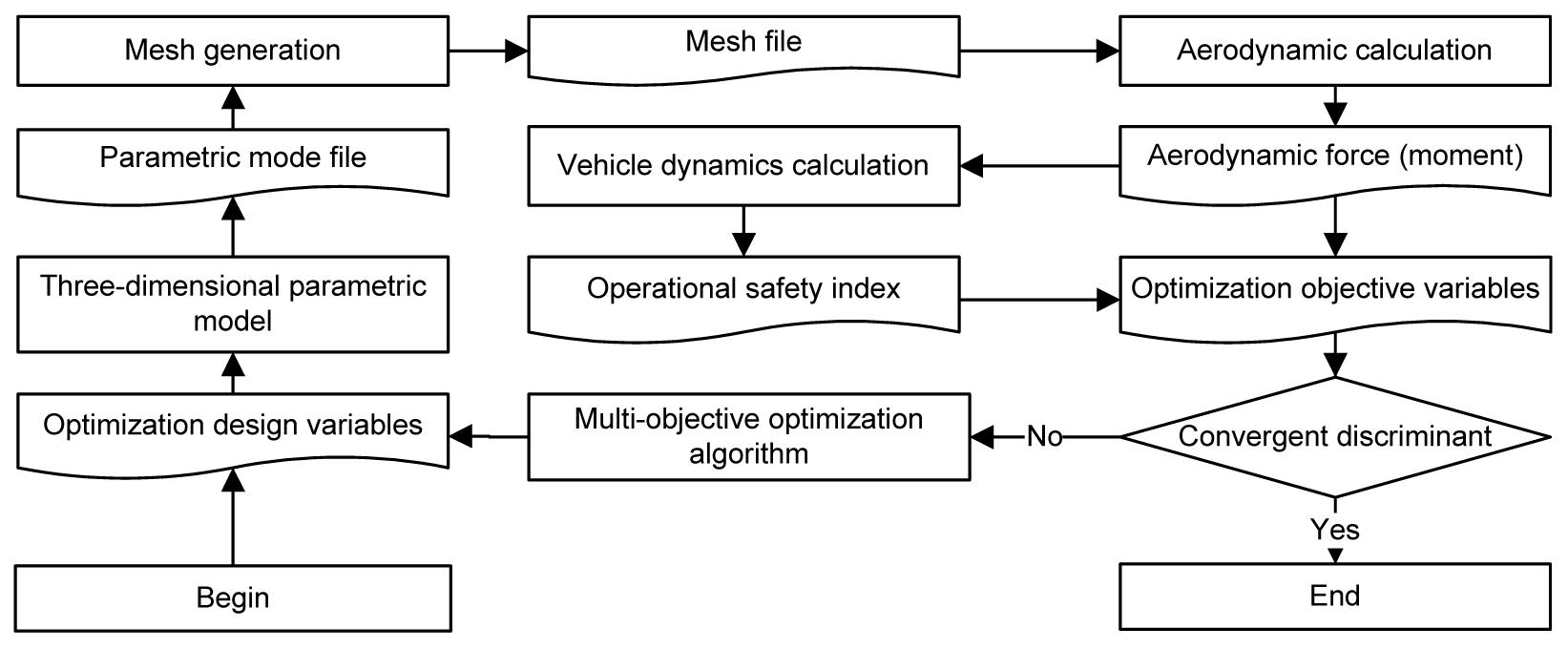
The multi-objective optimization design of the high-speed train head is the core technology of the high-speed train design. For some original head shape, users are often required to improve the aerodynamic performance (drag coefficient, lift coefficient, etc.), to reduce the energy consumption and improve the operational safety of the high-speed train. The automatic optimization design of the high-speed train head is of great significance. The multi-objective optimization design of the high-speed train head mainly involves the following aspects: the 3D parametric model design of the high-speed train, the aerodynamic calculation of the high-speed train (including mesh generation), the vehicle system dynamic calculation of the high-speed train, multi-objective optimization algorithms, system integration framework, and so on. The multi-objective optimization design process of the high-speed train head is shown in Fig. 1. The commercial 3D geometric modeling software or parametric design program can be used to set up the 3D parametric model. The commercial computational fluid dynamics software or self programming can be used for the aerodynamic calculation of the high-speed train. The commercial multi-body system dynamics software or self programming can be used for the vehicle system dynamic calculation of the high-speed train. Genetic algorithms or neural networks can be used for the optimization design of the high-speed train head. The commercial integration framework or batch program can be used for system integration.
Fig.1 Overall design flow for optimization
3. 3D parametric model of the train
The 3D parametric model of the high-speed train is established by CATIA. To achieve the automatic deformation of the head shape, the following three tasks need to be done successively:
Establish the entity model of the left half of a train head;
Parameterize the left half of the train head using the script file of CATIA;
Modify the parameter values in the script file of CATIA using a MATLAB program, and perform the deformation of the high-speed train head by running the script file.
3.1. Entity model of the left half of the train head
As the head shape of the high-speed train has a good symmetry, only the left half (or right half) portion of the train head needs to be modeled. The head shape of the high-speed train is quite complex, which cannot be described by simple analytic surfaces, but can be described by continuous splicing of some sub-surfaces. In this study, a number of B-spline surfaces are used to approximate the outer surface of the left half portion of the train head. B-spline surfaces are constituted by a series of B-spline curves, which are generated by a series of control points on the surface of the train head.
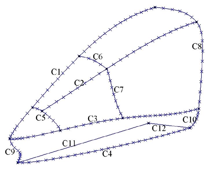
According to the head shape of a high-speed train, 162 control points are set up on the surface of the train head, which are used to build 12 B-spline curves. Then, the 12 B-spline curves can be used to build seven B-spline surfaces. After that, the left half of the train head is established, as shown in Fig. 2. To facilitate the later analysis, the B-spline curves are numbered C1 to C12, respectively.
Fig.2 Left half model of the train head
3.2. Parametric model of the high-speed train
Based on the entity model of the left half of the train head, a parametric model of the left half of the train head is established by the script file of CATIA. The coordinates of 162 control points of the left half portion can be recorded automatically to the script file by CATIA, and then the deformation of the head shape can be achieved by modifying the coordinates of 162 control points.
Based on the parametric model of the train head’s left half, the parametric model of a high-speed train with three carriages can be built through translation, symmetry, and so on, which can be recorded to the script file of CATIA.
3.3. Optimization design variables
To optimize the head shape of the high-speed train, five optimization design variables are selected, which correspond to the longitudinal symmetry line C1, the maximum horizontal contour line C3, the bottom horizontal contour line C4, the central auxiliary control line C7, and the nose height, respectively. With the increase of the streamlined length, the aerodynamic performance of the train will significantly be improved. Therefore, on the basis of a fixed streamlined length, the external shape of the train head is optimized to improve the aerodynamic performance and vehicle dynamic performance of the high-speed train.
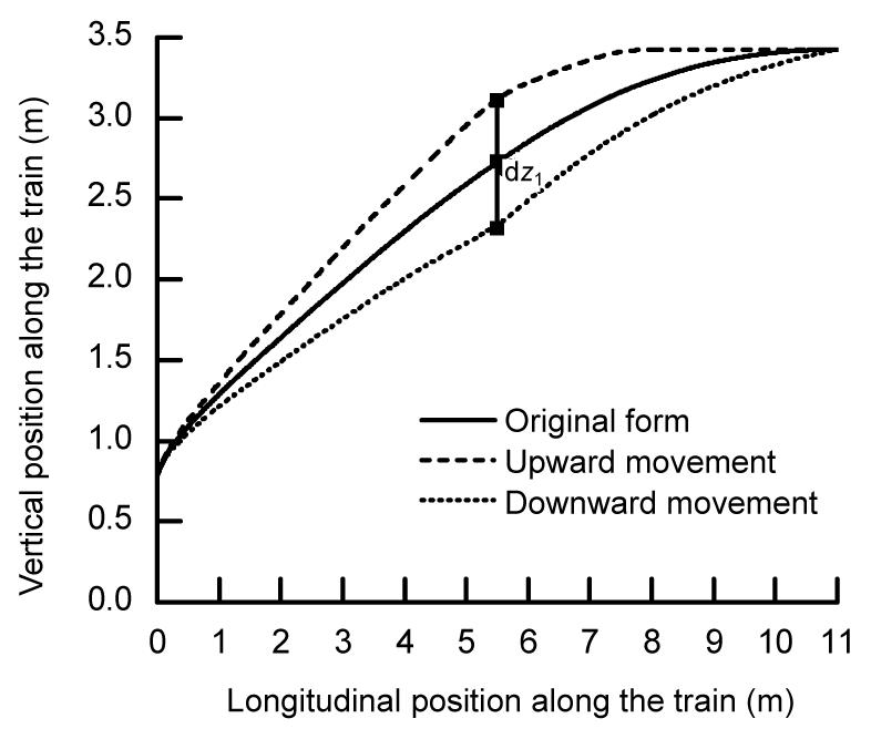
The deformation of C1 is carried out by changing the vertical coordinates of the control points of C1. The vertical coordinate of the midpoint of C1 is varying with dz1, while the vertical coordinates of both ends of C1 remain unchanged, i.e., the variation is 0. As to the points between the midpoint and the two end points, the variation of the vertical coordinates is in accordance with the linear law. Fig. 3 shows the deformation of C1, where the original form represents the initial form of C1, the upward movement means that dz1 is positive, and the downward movement means that dz1 is negative.
Fig.3 Deformation of the longitudinal symmetry line
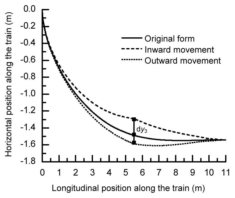
The deformation of C3 is carried out by changing the horizontal coordinates of the control points of C3. The horizontal coordinate of the midpoint of C3 is varying by dy3, while the horizontal coordinates of both two ends of C3 remain unchanged, i.e., the variation is 0. As to the points between the midpoint and the two end points, the variation of the horizontal coordinates is in accordance with the linear law. Fig. 4 shows the deformation of C3, where the original form represents the initial form of the C3, the inward movement (i.e., close to the longitudinal symmetry plane) means that dy3 is positive, and the outward movement (i.e., away from the longitudinal symmetry plane) means that dy3 is negative.
Fig.4 Deformation of the horizontal maximum control line
The deformation of C4 is similar to that of C3, and the optimization design variable is dy4, which will not be described in detail here.
The deformation of C7 is carried out to adjust concavity and convexity of the curve; therefore, the two ends of C7 need to be fixed and the deformation is becoming greater from the two end points to the midpoint. The following equation is adopted for the deformation:
,
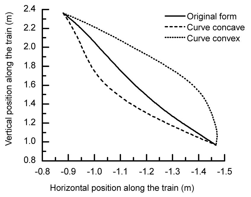
where n7 is the number of the control points of C7, y7,old(i) is the value of the horizontal coordinate before the deformation, y7,new(i) is the value of the horizontal coordinate after the deformation, and i is the number of the control point of C7. Fig. 5 shows the deformation of C7. The curve is convex when dy7>0 and concave when dy7<0.
Fig.5 Deformation of the central auxiliary control line C7
As to the variation of the nose height, the vertical coordinates of the control points of C9 need to be multiplied by a coefficient nscale. When nscale is greater than 1, the nose height becomes larger, and when nscale is less than 1, the nose height becomes smaller.
Note that when these curves mentioned above perform deformation, the relevant curves also need to be changed to ensure that the surface of the train head is continuous and smooth.
When optimization design variables are determined, the coordinates of the 162 control points in the script file of CATIA are modified by the MATLAB program, and then a new head shape of the high-speed train can be produced by running the script file.
4. Aerodynamic model
As a high-speed train running on the open track, the operating speed is generally not more than 400 km/h. The impact of the air density on the flow can be ignored without taking into account the trains passing each other or going through a tunnel. Therefore, the incompressible steady flow is adopted to simulate the flow field around the train, and the standard k-ε turbulence model is adopted, then the control equation of which can be expressed as follows (Versteeg and Malalasekera, 2007):
,
where ρ is air density, u is velocity vector, φ is the flow flux, S is the source item, and Γ is the diffusion coefficient.
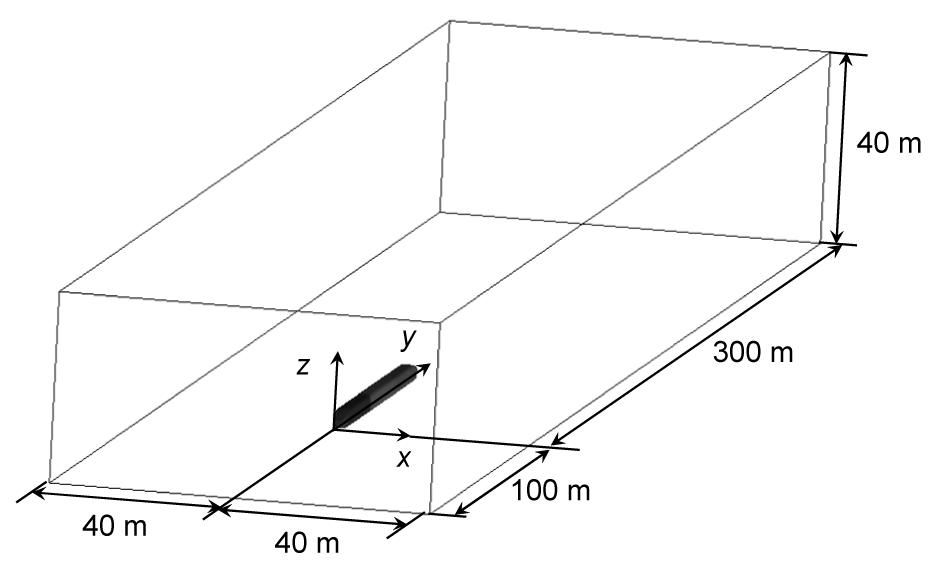
The train model for computing the flow field around the train is the 3D parametric model established in Section 3. The flow field computational domain is shown in Fig. 6. The left of the computational domain is set as the velocity inlet boundary, the right as the pressure outlet boundary, the two sides and the top as the symmetric boundary, and the train surface as the stationary wall boundary condition. The ground is set as the slip wall boundary condition, and the slip velocity as the train speed in order to simulate the ground effect. The triangle mesh is generated on the train surface, and the tetrahedral mesh is used for spatial meshes.
Fig.6 Flow field computational region
To perform the automatic optimization design of the high-speed train head, the mesh generation and the aerodynamics calculation of the high-speed train should be executed automatically. The script files of ICEM and FLUENT are used for the automatic mesh generation and aerodynamics calculation, respectively. The script files can be performed by the batch command.
5. Vehicle system dynamics model
The vehicle system dynamics mainly includes vehicle dynamics and wheel-rail contact. It is assumed that the carbody, bogie, and wheelsets are rigid, and their elastic deformation can be neglected. The equation of the vehicle system dynamics is
,
where M, C, and K are the mass, damping, and stiffness matrices of the train system, respectively. X is the generalized displacement vector of the system, is the generalized velocity vector of the system, is the generalized acceleration vector of the system, and F is the generalized load vector of the system, including the track excitation and aerodynamic loads.
A multi-body system dynamics model of the high-speed train is constructed by SIMPACK. The multi-body model of a single car is composed of one carbody, two bogies, four wheelsets, and eight tumblers. The rigid carbody, bogie, and wheelsets have six degrees of freedom each, while the tumbler has one. The dynamics model of a single car has 50 degrees of freedom. The train dynamics model with three carriages of “trailer car-motor car-trailer car” is built in this study, which has a total of 150 degrees of freedom. As to the trailer car and motor car, the degrees of freedom, the connection and constraints of the various components, the structure and most of the suspension parameters are exactly the same. The difference only exists in some local parameters such as the body mass, center of gravity height, and body rotational inertia. The wheel rail contact is in general the core of a railway model. LMA tread and T60 rail are used in this model. Track irregularities complicate the evaluation of the wheel unloading. Here, we adopt the measured track spectrum of a high-speed railway in China as the track irregularity.
The aerodynamic loads are dealt with as the external loads on the multi-body system dynamics model to analyze the operational safety of the high-speed train. Due to the translation and equivalent of the force, the pressure distribution can be simplified to a given point to obtain the concentrate forces and moments. The batch command can be used to call the file of SIMPACK named profile.ksh to realize the automatic calculation of vehicle system dynamics and the automatic output of the calculation results.
6. Multi-objective optimization algorithm
Currently, there are two major methods to solve the multi-objective optimization problems: the normalization approach and the non-normalized approach. The normalization approach transforms multiple objectives into a single objective so that the single-objective optimization methods can be used directly. When taking different weights, different solution sets can be computed to approximate the Pareto-optimal set. The normalization approach which has a poor computational efficiency is quite sensitive to the shape of the Pareto-optimal front. The non-normalization approach deals with the multi-objective optimization problems directly using the Pareto mechanism. The multiple objectives do not need to be converted to a single objective, and the shortcomings of the normalization approach are thus overcome. The non-normalization approach enables the forefront of the solution set to reach the Pareto front as close as possible, and tries to evenly cover the Pareto front. There are two major classes of the non-normalization algorithms, which are evolutionary multi-objective optimization (EMO) and direct search method (DSM) algorithms (Custódio et al., 2011; 2012; Zhou et al., 2011). Some commonalities exist in the design of DSM and EMO algorithms, such as searching in the neighborhood of existing solutions in order to find improvement, Pareto non-dominance, diversity maintenance strategies, and so on. However, there are also remarkable differences between DSM and EMO algorithms. DSM algorithms are deterministic, which can present a well established convergence analysis. EMO algorithms are randomized, and the convergence will be of probabilistic nature, also addressing global optimums (Custódio et al., 2012).
In this study, the algorithm NSGA-II is adopted, which is a widely used EMO method. NSGA-II proposes a fast non-dominated sorting approach with an elitist strategy, and replaces the sharing function approach with a crowded-comparison approach, which does not require any user-defined parameter for maintaining diversity among population members. The main loop of NSGA-II is described as follows (Deb et al., 2002):
A random parent population P0 of size N is created. The population is sorted based on the non-domination. Each solution is assigned a fitness (or rank) equal to its non-domination level. Thus, minimization of fitness is assumed. Then, the usual binary tournament selection, recombination, and mutation operators are used to create an offspring population Q0 of size N. Let t=0;
At the tth iteration, the combination of the random parent population Pt and the offspring population Qt is defined as the combined population Rt, viz. Rt=Pt∪Qt, and the size of Rt is 2N. Then the population Rt is sorted according to non-domination to get non-dominated front F1, F2, ···;
Sort all Fi based on the crowded comparison operator in descending order, and select the best N solutions to form the new population Pt+1;
The new population Pt+1 of size N is used for selection, crossover, and mutation to create a new population Qt+1 of size N;
If the termination condition is true, the procedure ends. Otherwise, t=t+1, and then turn to step 2.
7. Numerical simulation
There are 12 initial sample points in the design and 25 generations used in the optimization, so that 300 designs of the head shape optimization are obtained after the optimization.
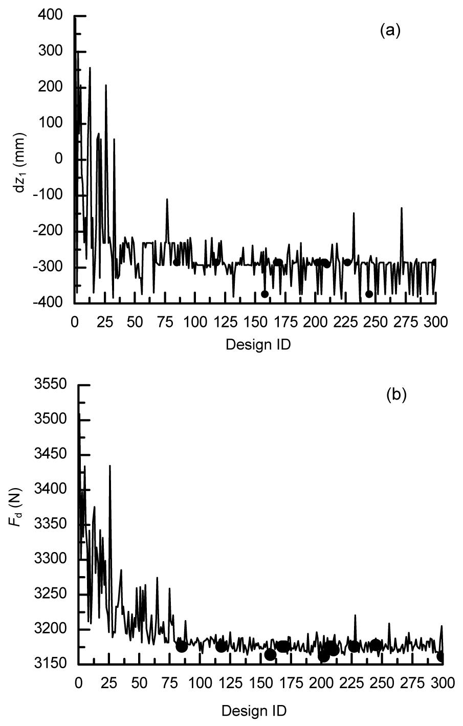
The histories of optimization design variables and optimization objectives for all the designs are presented in Fig. 7. Fig. 7a shows the history of dz1 for all the designs, and Fig. 7b illustrates the history of aerodynamic drag Fd for all the designs. We have the dot notation to present the Pareto-optimal solutions in the optimization process. As shown in Fig. 7, through repeated iterative calculation, the optimization design variables and optimization objectives tend to converge along with the optimization process, and the Pareto-optimal set and Pareto-optimal front are obtained.
Fig.7 Histories of dz1 (a) and Fd (b)
Fig. 8 shows the correlation coefficients between optimization objectives and optimization design variables. As shown in Fig. 8a, a positive correlation between the variables dz1, nscale, and the objective Fd within a certain range can be found, which means that a more concave longitudinal symmetry line or a shorter nose height would lead to a lower aerodynamic drag. A negative correlation between the variables dy3, dy4 and the objective Fd can be found, which means that when the horizontal maximum control line or the bottom horizontal contour line moves to the longitudinal symmetry, the aerodynamic drag would decrease. As shown in Fig. 8b, a positive correlation between each design variable (except the central auxiliary control line) and the load reduction factor within a certain range can be found. There is little impact of the variable dy7 on the aerodynamic drag or the load reduction factor.
Fig.8 Correlation between aerodynamic drag (a), load reduction factor (b) and optimization design variables
The obvious significant factors which affect the aerodynamic drag and load reduction factor are successively dy4, dy3, dz1, and nscale. In addition, from Fig. 8, each design variable has a bigger impact on the aerodynamic drag than that on the load reduction factor.
To further dig the nonlinear relationship between optimization objectives and optimization design variables, according to the analysis above, the variables dy4 and dy3, which are the most influential parameters, are chosen to conduct the response surface analysis with the aerodynamic drag. A 3D response surface of aerodynamic drag Fd, the variables dy4 and dy3 is shown in Fig. 9. No pure linear relationship exists among Fd, dy4, and dy3, which can never be attained by a usual optimum seeking method (Fig. 9). The aerodynamic drag Fd of the high-speed train shows a decreasing trend with the increase of dy4 or dy3, which is coincident with the results of Fig. 8.
Fig.9 Three-dimensional response surface
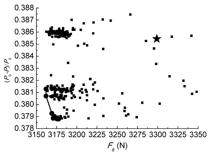
The convergence of the optimization variables in the image space for all the designs is shown in Fig. 10. In Fig. 10, (P0−P)/P0 indicates the load reduction factor, the curve connected by the dot notation “●” indicates the Pareto-optimal front of the multi-objective optimization of the high-speed train head, the pentagram “★” represents the aerodynamic drag force and load reduction factor corresponding to the initial head shape, and the square “■” denotes the aerodynamic drag force and load reduction factor corresponding to designs in the optimization process. It can be concluded that, after the multi-objective optimization design of the head shape, the performances of both the aerodynamic drag and load reduction factor have been improved. Compared with the initial head shape, the aerodynamic drag is reduced by up to 4.15% and the load reduction factor is reduced by up to 1.72% after optimization.
Fig.10 Pareto-optimal front of the head shape optimization
8. Conclusions
A parametric model of the high-speed train head is established in the present paper. The aerodynamic performance and vehicle dynamic performance of the high-speed train are calculated through the batch commands and script files. The multi-objective optimization algorithm NSGA-II is used for the automatic multi-objective optimization of the head shape, with the optimization objectives of the aerodynamic drag and load reduction factor. The proposed method can greatly reduce the design cycle of the head shape, and obtain a better head shape with good aerodynamic performance and vehicle dynamic performance.
The computational results show that a positive correlation between the variables dz1, nscale, and the objective Fd within a certain range can be found, and a negative correlation between the variables dy3, dy4, and the objective Fd, as well. There is a positive correlation between these four variables and the load reduction factor within a certain range. Through optimization, dy4 and dy3 are found to be the most influential parameters, and no linear relationship exists among the aerodynamic drag force and these two variables. After optimization, the aerodynamic drag is reduced by up to 4.15% and the load reduction factor is reduced by up to 1.72%.
[1] Aguilar Madeira, J.F., Rodrigues, H., Pina, H., 2005. Multi-objective optimization of structures topology by genetic algorithms. Advances in Engineering Software, 36(1):21-28.
[2] Brockie, N.J.W., Baker, C.J., 1990. The aerodynamic drag of high speed train. Journal of Wind Engineering and Industrial Aerodynamics, 34(3):273-290.
[3] Custdio, A.L., Madeira, J.F.A., Vaz, A.I.F., Vicente, L.N., 2011. Direct multisearch for multiobjective optimization. SIAM Journal on Optimization, 21(3):1109-1140.
[4] Custdio, A.L., Emmerich, M., Maderia, J.F.A., 2012. Recent developments in derivative-free multiobjective optimization. Computational Technology Reviews, 5:1-30.
[5] Deb, K., Agrawal, S., Pratap, A., Meyarivan, T., 2002. A fast and elitist multiobjective genetic algorithm: NSGA-II. IEEE Transactions on Evolutionary Computation, 6(2):182-197.
[6] Hemida, H., Krajnović, S., 2010. LES study of the influence of the nose shape and yaw angles on flow structures around trains. Journal of Wind Engineering and Industrial Aerodynamics, 98(1):34-46.
[7] Ikeda, M., Suzuki, M., Yoshida, K., 2006. Study on optimization of panhead shape possessing low noise and stable aerodynamic characteristics. Quarterly Report of RTRI, 47(2):72-77.
[8] Kikuchi, K., Tanaka, Y., Iida, M., Yamauchi, N., Yoshida, Y., Nakanishi, M., Takahashi, R., 2001. Countermeasures for reducing pressure variation due to train passage in open sections. Quarterly Report of RTRI, 42(2):77-82.
[9] Ku, Y.C., Rho, J.H., Yun, S.H., Kwak, M.H., Kim, K.H., Kwon, H.B., Lee, D.H., 2010. Optimal cross-sectional area distribution of a high-speed train nose to minimize the tunnel micro-pressure wave. Structural and Multidisciplinary Optimization, 42(6):965-976.
[10] Kwon, H.B., Jang, K.H., Kim, Y.S., Yee, K.J., Lee, D.H., 2001. Nose shape optimization of high-speed train for minimization of tunnel sonic boom. JSME International Journal Series C, Mechanical Systems, Machine Elements and Manufacturing, 44(3):890-899.
[11] Lee, J., Kim, J., 2008. Approximate optimization of high-speed train nose shape for reducing micropressure wave. Structural and Multidisciplinary Optimization, 35(1):79-87.
[12] Li, T., Zhang, J.Y., Zhang, W.H., 2013. A numerical approach to the interaction between airflow and a high-speed train subjected to crosswind. Journal of Zhejiang Universit-SCIENCE A (Applied Physics & Engineering), 14(7):482-493.
[13] Maeda, T., Kinoshita, M., Kajiyama, H., Tanemoto, K., 1989. Aerodynamic drag of Shinkansen electric cars (series 0, series 200, series 100). Railway Technical Research Institute, Quarterly Report, 30(1):48-56.
[14] Raghunathan, R.S., Kim, H.D., Setoguchi, T., 2002. Aerodynamics of high-speed railway train. Progress in Aerospace Sciences, 38(6-7):469-514.
[15] Schetz, J.A., 2001. Aerodynamics of high-speed trains. Annual Review of Fluid Mechanics, 33(1):371-414.
[16] Shao, X.M., Wan, J., Chen, D.W., Xiong, H.B., 2011. Aerodynamic modeling and stability analysis of a high-speed train under strong rain and crosswind condition. Journal of Zhejiang University-SCIENCE A (Applied Physics & Engineering), 12(12):964-970.
[17] Sun, Z.X., Song, J.J., An, Y.R., 2010. Optimization of the head shape of the CRH3 high speed train. Science China Technological Sciences, 53(12):3356-3364.
[18] Suzuki, M., Ikeda, M., Yoshida, K., 2008. Study on numerical optimization of cross-sectional panhead shape for high-speed train. Journal of Mechanical Systems for Transportation and Logistics, 1(1):100-110.
[19] Versteeg, H.K., Malalasekera, W., 2007. An Introduction to Computational Fluid Dynamics. The Finite Volume Method. Prentice Hall,New Jersey, America :
[20] Yao, S.B., Guo, D.L., Yang, G.W., 2012. Three-dimensional aerodynamic optimization design of high-speed train nose based on GA-GRNN. Science China Technological Sciences, 55(11):3118-3130.
[21] Zhou, A., Qu, B.Y., Li, H., Zhao, S.Z., Suganthan, P.N., Zhang, Q.F., 2011. Multiobjective evolutionary algorithms: A survey of the state of the art. Swarm and Evolutionary Computation, 1(1):32-49.
Open peer comments: Debate/Discuss/Question/Opinion


Open peer comments: Debate/Discuss/Question/Opinion
<1>