Abstract: The mechanical behavior of concrete-filled glass fiber reinforced polymer (GFRP)-steel tube structures under combined seismic loading is investigated in this study. Four same-sized specimens with different GFRP layout modes were tested by a quasi-static test system. Finite element analysis (FEA) was also undertaken and the results were presented. Results of the numerical simulation compared well with those from experimental tests. Parametric analysis was conducted by using the FE models to evaluate the effects of GFRP thickness, axial compression rate, and cross sectional steel ratio. The experimental and numerical results show that the technique of GFRP strengthening is effective in improving the seismic performance of traditional concrete-filled steel tubes, with variations related to different GFRP layout modes.
Darkslateblue:Affiliate; Royal Blue:Author; Turquoise:Article
Article Content
1. Introduction
Concrete-filled steel tube (CFT) structures have been widely used in tall buildings and arch bridges around the world. The steel tube and concrete work together, to resist applied loads. The external steel tube provides confinement for the inner concrete which in turn delays local buckling of the tube and so increases the stability and strength of the column as a system. Previous studies have shown that CFT structural members have a number of distinct advantages over equivalent steel, reinforced concrete, or steel-reinforced concrete members, especially for seismic resistance. These advantages include high stiffness and strength, large energy absorption and enhanced ductility and stability (Shams and Saadeghvaziri, 1997; Morino, 1998; Uy, 1998; Schneider, 1998; Zhang and Shahrooz, 1999; Liang and Uy, 2000; Bradford et al., 2002). However, since the Poisson’s ratio of steel is higher than that of concrete, a separation, caused by differential expansion between the steel tube and the concrete will occur at the early stages of loading (Roeder et al., 1999), which will inevitably delay the activation of the confinement mechanism. Furthermore, exposed steel is doomed to a limited service life and high maintenance costs, especially if it is used in harsh marine environments (Brown and Powers, 1986; Lasa et al., 1998).
Another similar structure is the concrete-filled fiber reinforced polymer (FRP) tube (CFFT). The main advantage of this composite construction is the optimal use of materials based on their mechanical properties and corrosion resistance (Mirmiran and Shahawy, 1996). FRP with its extremely high tensile strength provides a more effective confinement for concrete and its laminate structure can be controlled to provide different proportions of strength and stiffness in the longitudinal and transverse directions. A FRP jacket withstands a harsh, salty environment with high internal temperature, direct sunlight, moisture, vapor, and seawater (Chajes et al., 1995; Steckel et al., 1998) indicating that CFFT overcomes the defect of low corrosion resistance of CFT and can be used in some extreme environments. However, since FRP is a brittle material, if it breaks suddenly under accidental loads, such as an earthquake or an impact, the strength of the whole system would drop dramatically (Fam and Rizkalla, 2001), inevitably resulting in insufficient ductility compared with the equivalent CFT structure.
Following extensive studies on CFT and CFFT columns, a new CFT structure, termed concrete-filled FRP-steel tube (FRP-CFT), has been introduced (Wang and Zhao, 2003), which is made by filling a steel tube with concrete and wrapping the tube with FRP sheet. FRP wrapping enables the column to develop multi mechanical properties and acts as an anti-corrosion jacket for the steel tube, and the steel tube, providing compensation for the brittleness of the FRP, assures the ductility of the whole system.
Experimental and theoretical research on concrete-filled carbon fiber reinforced polymer (CFRP)-steel tube (CFRP-CFT) has been carried out. (Gu and Zhao, 2007) conducted experiments on concrete-filled hoop CFRP-steel tube under axial compression. Specimens included long and short columns. The results on short columns showed a significant improvement in the loading capacity compared with the equivalent CFT structure; however, with the increase in the slenderness ratio, the strengthening effect of CFRP declined. When the slenderness ratio reached a certain value, there was no strengthening effect of CFRP. Gu et al. (2006) deduced formulas for the loading capacity under axial compression of concrete-filled CFRP-steel tubes of different slenderness, which showed good agreement with experimental results. Wang et al. (2008) reported on torsion and bending experiments with concrete-filled CFRP-steel tube. The results showed that both circumferential and longitudinal CFRPs can enhance the ultimate torsion capacity of the specimens. Longitudinal CFRP enhances the ultimate moment and flexural stiffness of the composite members significantly. Tao and Yu (2006) treated CFRP as a retrofitting technique for repairing CFT structures damaged by fire. A number of tests for compression and bending were conducted. The results proved that CFRP strengthening can effectively improve the mechanical properties of a damaged CFT structure.
2. Aim and scope
Another FRP, GFRP, which is being widely used for strengthening old or damaged infrastructure, can also be used in combination with a CFT column. Compared with CFRP, GFRP has notable advantages (Nishizaki and Meiarashi, 2002; Bousias et al., 2004; Huang et al., 2005a; 2005b; Gadve et al., 2009).
The ultimate elongation rate of GFRP is higher than that of CFRP. By using this property, GFRP combined structures should have more deformable capacity than CFRP ones.
GFRP is an electronic isolation material and so, when combined with steel, it can protect it from the electrochemical corrosion which readily occurs on steel or steel reinforced concrete structures in marine environments.
The thermal expansion coefficient of GFRP is similar to that of steel, which eliminates thermal stress at the interface with the steel surface.
The cost of GFRP is lower and its production process is well-established.
By using these characteristics of GFRP, a new FRP-CFT, termed concrete-filled GFRP-steel tube (GFRP-CFT), is proposed. In this paper, we describe an investigation of the mechanical properties of a GFRP-CFT structure member under cyclic loading. A quasi-static test was developed and the influence of different GFRP layout modes was analyzed. Finite element models were applied based on the experimental process and the seismic performance of GFRP-CFT was studied at varying GFRP thicknesses, axial compression ratios, and cross sectional steel ratios.
As a novel combining structure, GFRP-CFT is a three-phase composite structure. Investigations of the failure modes and the GFRP strengthening mechanisms under cyclic loading are essential when using. A GFRP-steel composite jacket can also be used as a retrofitting tool for old or damaged concrete structures. It might also be used as an anti-corrosion jacket for structures in marine environments, and that will be investigated in future study based on this research.
3. Experimental
3.1. Specimens and apparatus
Four same-sized CFT or GFRP-CFT specimens were prepared as listed in Table 1, where K-0 is ordinary CFT as reference. H-1G, L-1G, and B-2G are circumferential, longitudinal, and bi-directional GFRP wrapping specimens, respectively. For all specimens, the lengths are 1700 mm and the outer diameters and thickness of the steel tubes are 114 mm and 3.5 mm, respectively.
Table 1
Parameters of specimens
Serial number
GFRP layers/thickness
GFRP wrapping mode
Axial compression ratio
K-0
–
–
0.14
H-1G
1/0.354 mm
Circumferential
L-1G
1/0.354 mm
Longitudinal
B-2G*
2/0.708 mm
Bi-direction
*Bi-direction wrapping mode is longitudinal wrapping inside and circumferential wrapping outside
Commercial C40 concrete is used with an average compressive strength of 38.70 MPa for 150 mm cubic specimens and a compressive initial elastic modulus of 32 500 MPa. Yield stress of the seamless steel tube is 245 MPa, and the elastic modulus is 206 000 MPa. The parameters of the glass fiber are described in Table 2.
Table 2
Mechanical properties of glass fiber
Thickness (mm)
Mass per unit area (g/m2)
Tensile strength (MPa)
Tensile modulus (MPa)
Limit elongation (%)
0.354
900
≥1500
≥72 000
≥2.0
Specimens were constructed as follows. Seamless steel tubes were cut to the designed length, ensuring that the cross-sections of the two ends were perpendicular to the axis. A steel plate was then welded onto one end of the tube and the tube was filled with concrete. After 28 d the redundant concrete expanded from the tube was cut off and another steel plate was welded to the free end. Lastly, the surfaces of the steel tubes were polished before affixing the GFRP sheets by daubing the surface of the tubes with resinous glue and wrapping the GFRP sheets around them, scraping the surface of the sheets to squeeze out air between them and the steel tubes. To assure that the GFRP sheets were immersed in resinous glue. After 48 h, the specimens were ready for testing.
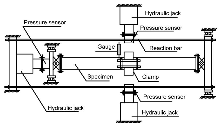
Specimens were installed horizontally and both ends were pinned, as shown in Figs. 1 and 2. The multiple loads included cyclic lateral load and axial compression. Lateral load was provided by two vertical hydraulic jacks and axial compression was provided by a horizontal hydraulic jack, which were both measured by load cells. The axial compression was applied to a pre-fixed value and kept the compression ratio stable at 0.14 during the testing period. For convenience of comparison, the axial compression ratio n calculation method for CFT is used for all specimens, defined as follows:
,
where N is the applied axial load, Nu,cr is the ultimate axial loading capacity, which can be determined by
,
where φ=0.0001λ2−0.228λ+1.277 is the stability coefficient and λ is the slenderness ratio. Asc is the cross-sectional area, Asc=As+Ac, where Ac and As are the cross sectional areas of the concrete and steel tubes, respectively. Fscy=(1.14+1.02ζ)fck is the strength index of concrete, ζ=Asfy/(Acfc), in which fc and fs are the axial compressive strengths of concrete and the yield stress of the steel tube, respectively.
Fig.1 Loading schema
Fig.2 Loading system
Cyclic load is applied in a perpendicular direction. The force-displacement double control law is used, with force control before yield of the specimen and displacement control after yield. Loading and displacing steps are 5 kN and 10 mm, respectively. The loading law is shown in Fig. 3.
Fig.3 Loading law (a) Load control; (b) Displacement control
3.2. Test observations
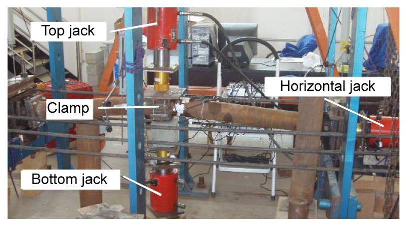
In testing, local buckling of the steel tube can be observed in mid-span for K-0 when the deflection reaches a maximum. The failure form is shown in Fig. 4a. For specimen H-1G, several crannies appear in the epoxy, accompanied by a cracking sound when the deflection reaches about 20 mm. These crannies occur in mid-span and surround the tube, but rupture of the fiber was not observed in testing. The corresponding broken mode after testing is shown in Fig. 4b. The first signs of distress in specimens L-1G and B-2G are fracture of the GFRP at the top and the bottom. For L-1G, it is at the first peak of the 55th cycle, that is, Δ=40 mm. Fracture of GFRP at the top is followed by breaking of the GFRP at the bottom at the second peak, accompanied with a loud and clear cracking sound. The GFRP sheet near the ruptures debonds with the tube surface. After that, fragmentary cracking sounds can be heard as the deflection increases. The corresponding broken mode is shown in Fig. 4c. For specimen B-2G, the first fracture occurs in the 62nd cycle, that is, Δ=50 mm. It is later than that of specimen L-1G, but is also accompanied with a loud and clear cracking sound. As shown in Fig. 4d, because of restriction by the outer circumferential GFRP the broken GFRP sheet near the crannies does not de-bond from the steel tube. In testing, local buckling of the steel tube is hardly observed, indicating that circumferential GFRP provides an effective confinement for the inner steel tube. The development of local buckling of the steel tube, which would rapidly increase the strain in attached longitudinal GFRP in the buckling region, is restrained by the circumferential GFRP; as a result, the longitudinal GFRP of B-2G fractures later than that of L-1G.
Hysteresis curves for all specimens from the tests are shown in Fig. 5. Fig. 5a is for K-0, which is a typical hysteresis curve for a general CFT structure. Note that the hysteresis loops for the different load cycles partly overlap and each summit point falls on the next loop. The outline of the entire hysteresis curve is smooth. There are reasonable similarities in the form of the hysteresis curves of K-0 and H-1G, showing that circumferential GFRP wrapping makes little contribution to seismic performance in this test. Since GFRP is an anisotropic material, its tensile strength and elastic modulus in the fiber direction are much higher than those in other directions, and circumferential GFRP strengthening provides confinement in the hoop direction and restrains local buckling of the steel tube, resulting in improved loading capacity. However, this strengthening effect becomes weaker as the length of column increases. In this test, where the slenderness ratio for all specimens is 14.9, the strengthening effect from circumferential GFRP is not notable. Therefore, there is no obvious difference between the hysteresis curves for K-0 and H-1G.
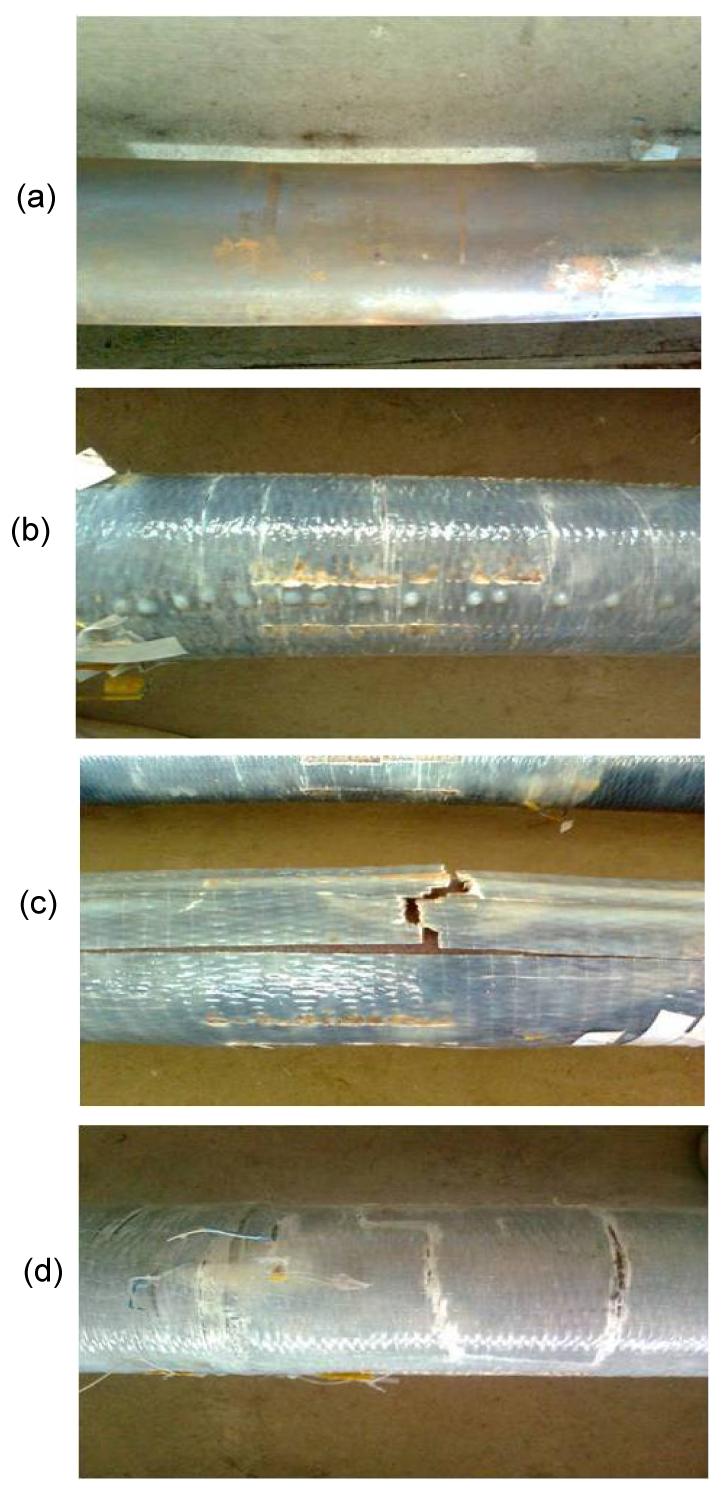
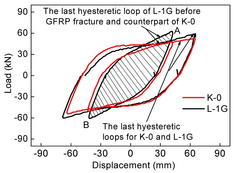
However, the hysteresis curves change very obviously for L-1G and B-2G compared with those for K-0 (or H-1G). Their outlines can be described by combining two different hysteresis loops. Since there are reasonable similarities in form of these two hysteresis curves, only the hysteresis curve for L-1G is taken for illustration here (Fig. 6). Before GFRP failure, the hysteresis curve for L-1G is in the dark loop and the longitudinal GFRP strengthening effect is mainly reflected there. Two load summit points A and B are located outside the equivalent loop of K-0, showing that the loading capacity for specimen L-1G is enhanced; the area of the dark loop is much larger than that of the K-0 counterpart, indicating that specimen L-1G has a better energy dissipation ability than K-0. However, as deflection develops, the shape of the hysteresis loop reverts to that of K-0 after the longitudinal GFRP fractures and the GFRP strengthening effect fades away at this time.
Fig.6 Hysteresis curves for L-1G and K-0
3.4. Loading carrying capacity
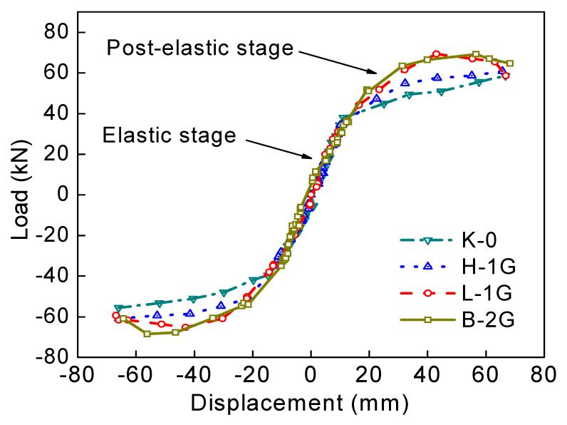
Comparison of the skeleton curve of specimen K-0 with those of specimens H-1G, L-1G, and B-2G shows the remarkably beneficial effect of GFRP wrapping on the strength of columns (Fig. 7). It can be seen that all load-displacement (P-Δ) curves overlap closely at the elastic stage, showing that GFRP strengthening cannot improve elastic stiffness effectively for every structure. When entering the post-plastic stage, the strengthening effect appears gradually. Tangential stiffness for GFRP wrapping specimens improves to different extents compared with that for K-0. Since GFRP hoop strengthening is not very effective for these long columns, the loading improvement for H-1G is the lowest among the three GFRP wrapping specimens. For L-1G, the longitudinal GFRP can work with the steel tube under bending and provides effective stress compensation for it in the tensile zone, eventually improving post-elastic stiffness and loading capacity effectively for the whole structure. For B-2G, bi-directional GFRP can both restrain local buckling and strengthen the steel tube in the tensile direction. Thus, its ultimate strength improvements are the highest among all the specimens. The load summit also occurs later than in other GFRP wrapping specimens due to the confinement of the steel tube by the hoop GFRP.
Fig.7 Skeleton curves for different FRP wrapping modes
3.5. Equivalent rigidity degradation
Damage of the specimens can be assessed by the degradation of the equivalent rigidity K, which is the slope of the line joining the origin and the loading summit point of hysteresis loop, which can be defined as
,
where Pmax is the loading summit value of each cyclic loop, and Δc is the corresponding displacement.
The variation of K is shown in Fig. 8. K decreases rapidly with increased displacement. Compared with specimen K-0, GFRP strengthened specimens have low equivalent rigidity degradation before GFRP failure, especially for specimens L-1G and B-2G at the post-elastic stage.
Fig.8 Stiffness degradation for different GFRP wrapping specimens
3.6. Energy dissipation capacity
In order to evaluate the energy dissipation capacity of all specimens, a normalized energy dissipative coefficient E is calculated by
,
where SABCD is the area of the hysteresis curve (the outlines of the whole hysteresis curve used to calculate E are marked blue in Fig. 9), SΔOBF and SΔODG are the areas of the corresponding triangles (marked red in Fig. 9) (in the web version). Because GFRP strengthening enlarges the areas of the hysteresis curves, energy dissipation capacity for GFRP wrapping specimens improves to different levels compared with that of specimen K-0. Results for calculating E are shown in Table 3.
Fig.9 Schematic sketch of E calculation for L-1G
Table 3
Energy dissipation capacity for GFRP strengthened CFT
Serial number
E
Improvement (%)
K-0
2.23
H-1G
2.29
2.7
L-1G
2.47
10.8
B-2G
2.61
17.0
4. Finite element investigation
4.1. Finite element modeling
In order to study the influence of GFRP wrapping on the seismic properties of the structure, ABAQUS finite element analysis (FEA) software is used for numerical analyses. Due to the symmetry of loads and structure geometry, semi-structures of CFT and GFRP-CFTs with different GFRP layout modes, are modeled. The experimental program is completely emulated. In the modeling process, a concrete damage plastic model provided by the ABAQUS material library is used to realize the damage processes in the concrete and standard elastic-plastic model, and the von Mises yield criterion is used for the steel tube. GFRP is treated as an elastic material with a Young’s modulus of 60 000 MPa. The fracture of GFRP is emulated by using the Hashin damage laws. Interface constraints between different materials (GFRP, steel tube and concrete) use binding constraints (tie) which assume no relative sliding between interfaces.
Concrete is modeled with an eight-node linear reduced integration with an hourglass control solid element (C3D8R). This element has large deflection and strain capabilities. The steel tube was modeled with an eight-node continuum shell with a reduced integration and hourglass control membrane element (SC8R). For GFRP, a four-node membrane with reduced integration and an hourglass control element (M3D4R) is used.
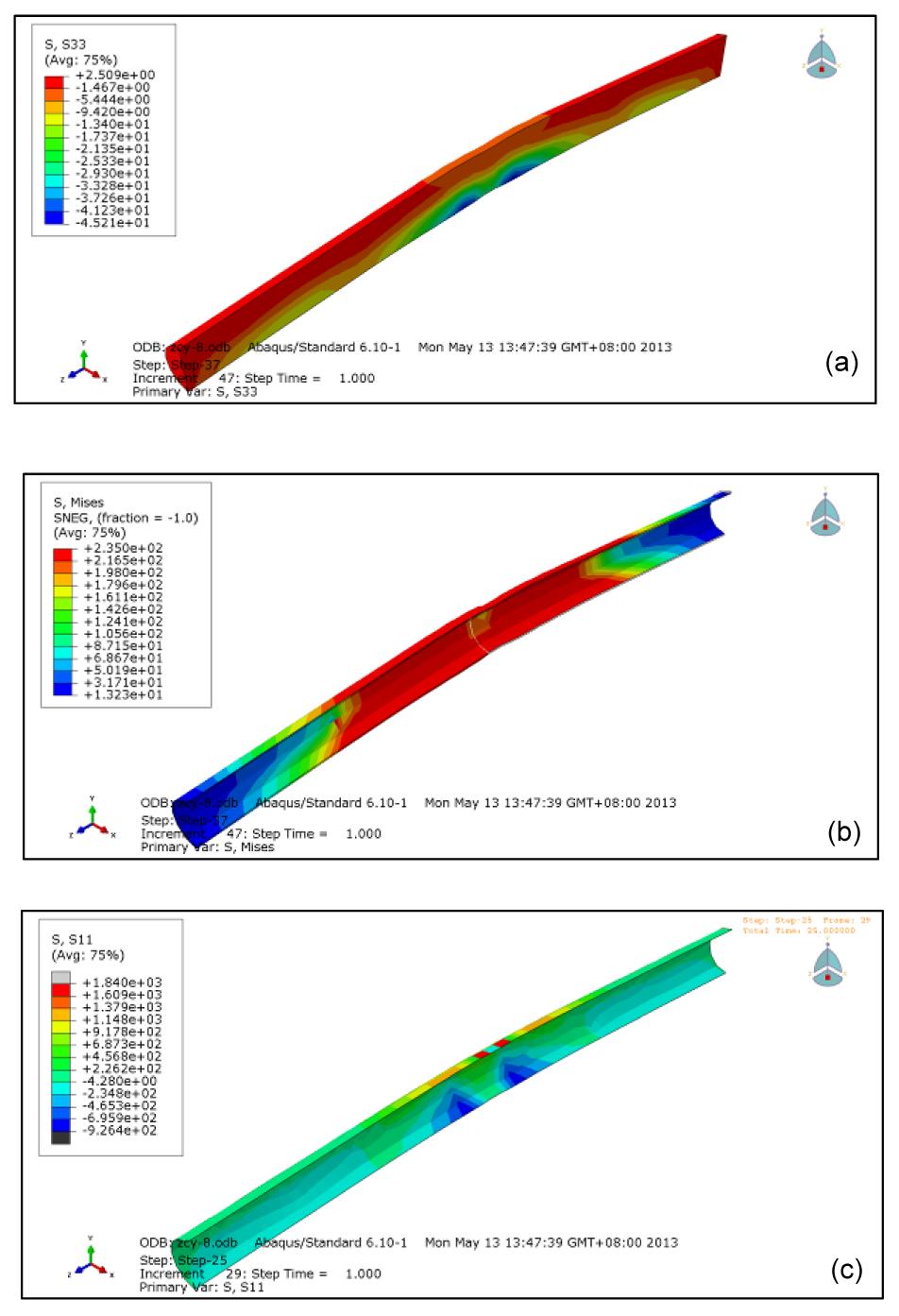
The calculated stress contours of the concrete, steel tube and GFRP are shown in Figs. 10a, 10b, and 10c, respectively. Obvious protrusions occur on both sides of the load-acting position on the steel tube under combined loads of axial and vertical pressures, indicating that buckle will occur at that region.
Fig.10 Concrete longitudinal stresses distribution (a), steel tube von Mises stresses distribution (b), and GFRP longitudinal stresses distribution (c)
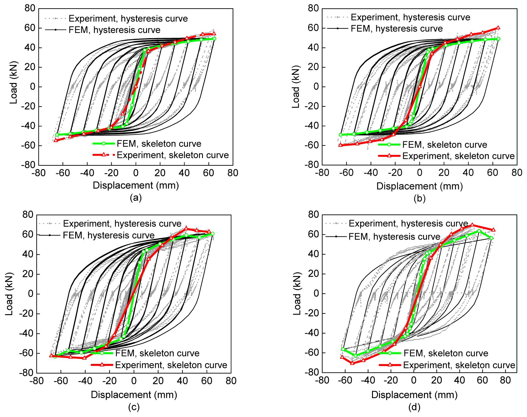
Comparisons of hysteresis curves from experiment and numerical simulations are shown in Fig. 11, in which green and red curves (in the web version) are the skeleton curves. From these figures, the stiffness of hysteresis curves at both elastic and post-elastic stages from ABAQUS simulations is a little higher than that from experiment, with an average error of 5%. This is mainly because binding constraints between the interfaces of different materials increase the integral rigidity of the FE models, resulting in FE models stiffer than the real structures. In reality, relative sliding does exist between the interfaces, but if it were perfectly simulated, the cost of calculation would be excessive. However, the entire shapes of the hysteresis curves from ABAQUS simulation are coincident with those from experiment and the trends of two corresponding skeleton curves are nearly identical, indicating that the finite element models are reasonably built and can be used for the parameter study.
Fig.11 Comparison of experimental and simulation hysteresis curves of all specimens (a) K-0; (b) H-1G; (c) L-1G; (d) B-2G
4.2. Parametric analysis
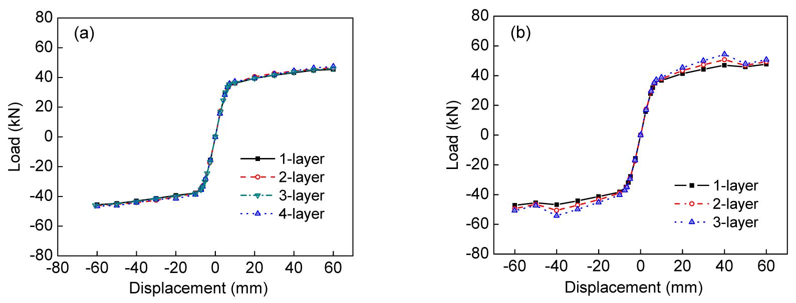
In order to investigate the influences of GFRP thickness on seismic performance, FE models with different GFRP thicknesses are built. Simulation results are shown in Fig. 12. Compared with CFT, loading capacity for the GFRP-CFTs is improved and the improvement is related to the GFRP wrapping direction and thickness. Circumferential GFRP thickness has little effect to the ultimate loading capacity, with less than a 1% improvement for the four circumferential GFRP layers. However, the ultimate loading capacity improves significantly with the increase in the longitudinal GFRP thickness. At the same time, the tangential stiffness of the post-elastic stage of the skeleton curve improves correspondingly.
Fig.12 Skeleton curves for specimens with different circumferential/longitudinal GFRP thickness (a) Circumferential GFRP; (b) Longitudinal GFRP
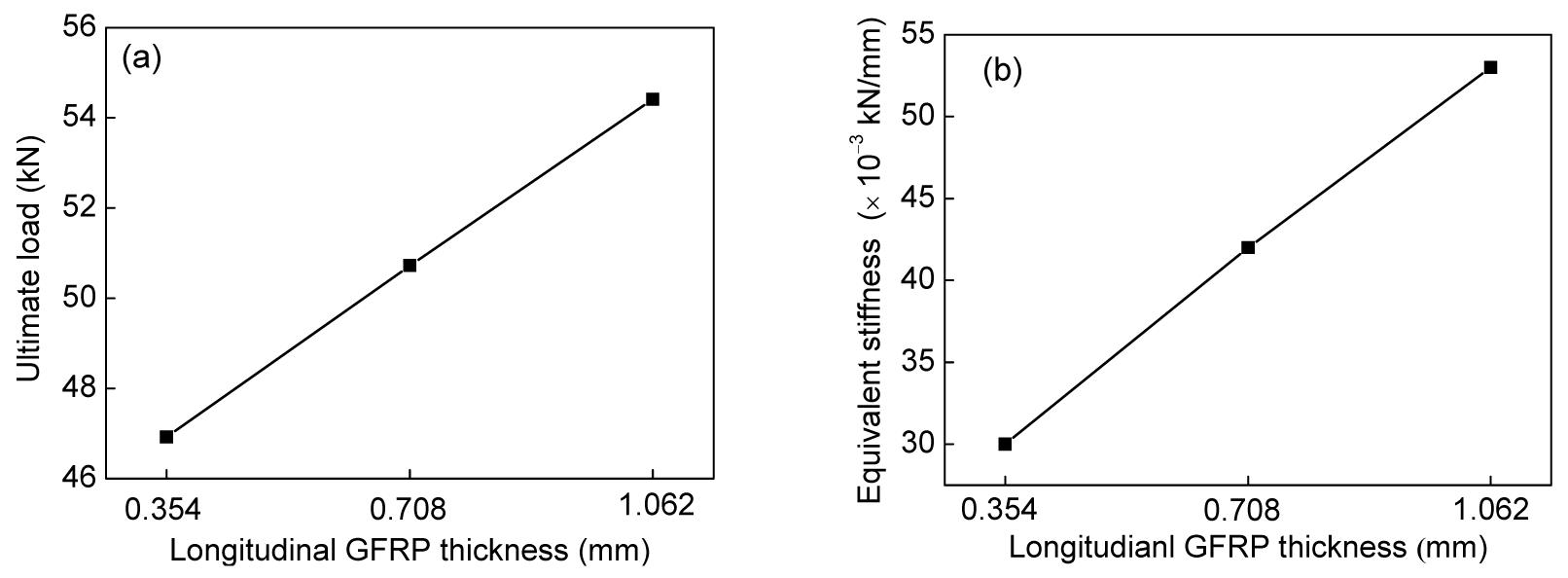
The relationship of the thickness of longitudinal GFRP to equivalent stiffness and ultimate loading capacity is shown in Fig. 13, indicating that equivalent stiffness and ultimate loading capacity are almost linearly related to the increase in longitudinal GFRP thickness.
Fig.13 GFRP layers-ultimate load (a) and GFRP layers-equivalent stiffness (b) relationships Note: The longitudinal thicknesses of 0.354, 0.708, and 1.062 mm are for 1-layer, 2-layer, and 3-layer GFRPs, respectively
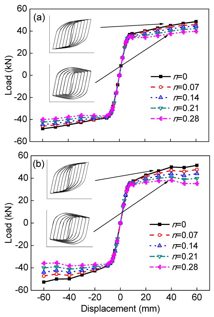
Skeleton curves under different axial compression ratios n are shown in Fig. 14, in which the hysteresis curves under axial compression ratios of 0 and 0.28 are given. As the axial compression ratio increases, the loading capacity and tangential stiffness of the skeleton curve in the post-plastic stage degrade significantly. The shape of the hysteresis curve under high axial compression also changes. The load summit occurs earlier and the post strength degrades more with each hysteresis loop as n increases.
Fig.14 Skeleton curves of H-1G (a) and L-1G (b) under different axial compression ratios
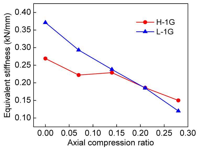
Fig. 15 shows the relationship between equivalent tangential stiffness in the post-plastic stage of the skeleton curve and axial compression ratios. It indicates that for the longitudinal GFRP layout specimens, as the axial compression ratio increases, the equivalent tangential stiffness declines almost linearly, but for the circumferential GFRP wrapping specimens, the decline is non-linear and the decreasing amplitude is low.
Fig.15 Relationship of equivalent tangential stiffness for elastic-plastic stage of the skeleton curve and axial compression ratios
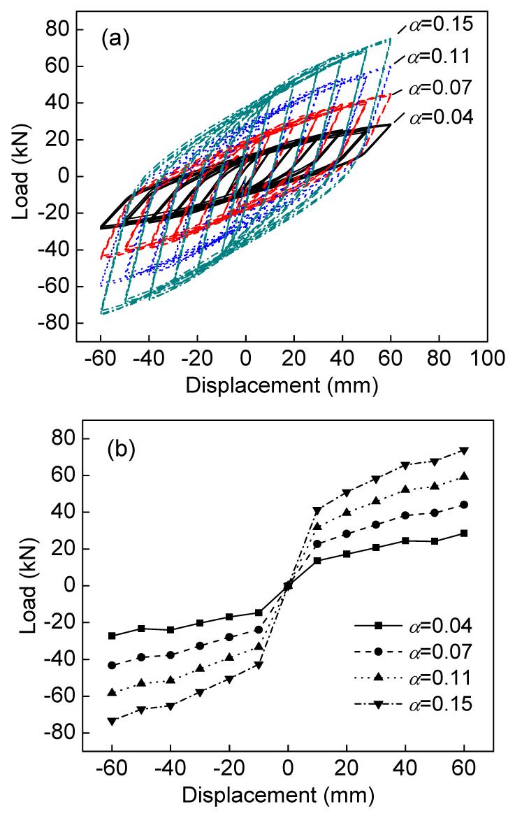
Varying the cross sectional steel rate of L-1G by changing the thickness of the steel tube (keeping the inner diameter stable and varying the outer diameter), gives the hysteresis and skeleton curves as shown in Fig. 16. All hysteresis curves get plumper as the cross sectional steel ratio (α) increases; elastic and post-elastic stiffness and loading capacity also improve.
Fig.16 Hysteresis (a) and skeleton (b) curves with different steel rates of L-1G
5. Conclusions
The mechanical properties of the GFRP-CFT are improved compared with CFT and that improvement is also related to the GFRP layout modes. GFRP hoop wrapping can inhibit local buckling of the steel tube while longitudinal wrapping inhibits bending. GFRP strengthening can also improve the initial strength of the composite column.
Seismic performance for GFRP-CFT improves because of the GFRP strengthening. The equivalent rigidity degeneration rates for GFRP-CFTs, especially for longitudinal and bi-directional GFRP layout ones, are lower than that of CFT. The normalized energy dissipation coefficients for specimens with circumferential, longitudinal, and bi-direction GFRPs improve by 2.7%, 10.8% and 17.0%, respectively.
A plastic-damage model for concrete and the Hashin damage laws for fiber can be used to model GFRP-CFT which is a three-phase composite structure. The reinforcement effect of GFRP is mainly reflected at the post-plastic stage. The longitudinal and bi-directional GFRP layouts are more effective than the circumferential one for improving the bending strength of a long column. As the GFRP thickness increases, the ultimate bearing capacity and skeleton curve tangential stiffness for the post-plastic stage improve linearly, causing a corresponding increase in the area of the hysteresis loop representing energy dissipation capacity.
The axial compression ratio and steel rate have obvious effects on GFRP-CFT seismic behavior: post-elastic stiffness and post-strength degrade with the increase of the axial compression ratio. The decline for longitudinal GFRP wrapping specimens is greater than that for circumferential GFRP wrapping ones. The higher the steel rate, the more energy dissipation capacity the structure has.
[3] Brown, R.P., Powers, R.G., 1986. Update on the Use of Conductive Materials for Cathodic Protection of Steel in Concrete. NACE,Houston, USA :264.1-264.8.
[4] Chajes, M.J., Thomson, T.A., Farschman, C.A., 1995. Durability of concrete beams externally reinforced with composite fabrics. Construction and Building Materials, 9(3):141-148.
[5] Fam, A.Z., Rizkalla, S.H., 2001. Confinement model for axially loaded concrete confined by circular fiber-reinforced polymer tubes. ACI Structural Journal, 98(4):451-461.
[6] Gadve, S., Mukherjee, A., Malhotra, S.N., 2009. Corrosion of steel reinforcements embedded in FRP wrapped concrete. Construction and Building Materials, 23(1):153-161.
[7] Gu, W., Zhao, Y.H., 2007. Experimental study on concrete filled CFRP-steel tube columns with axial compression. China Civil Engineering Journal, (in Chinese),40(11):23-28.
[8] Gu, W., Zhao, Y.H., Shang, D.W., 2006. Load carrying capacity of concrete filled CFRP-steel tubes under axial compression. Engineering Mechanics, (in Chinese),23(1):149-153.
[9] Huang, Y.L., Hung, C.H., Yen, T., Wu, J.H., Lin, Y., 2005. Strengthening reinforced concrete beams using prestressed glass fiber-reinforced polymer-Part II: Analytical study. Journal of Zhejiang University-SCIENCE A, 6(8):844-852.
[10] Huang, Y.L., Wu, J.H., Yen, T., Hung, C.H., Lin, Y., 2005. Strengthening reinforced concrete beams using prestressed glass fiber-reinforced polymer-Part I: Experimental study. Journal of Zhejiang University-SCIENCE A, 6(3):166-174.
[11] Lasa, I.R., Powers, R.G., Kessler, R.J., 1998. Practical Application of Cathodic Protection Systems for Reinforcing Steel Substructures in Marin Environment, Proceedings of the International Seminar on Repair and Rehabilitation of Reinforced Concrete Structures,:16-31.
[12] Liang, Q.Q., Uy, B., 2000. Theoretical study on the post-local buckling of steel plates in concrete-filled box column. Computers & Structures, 75(5):479-490.
[13] Mirmiran, A., Shahawy, M., 1996. A new concrete-filled hollow FRP composite column. Composites Part B: Engineering, 27(3-4):263-268.
[14] Morino, S., 1998. Recent developments in hybrid structures in Japan—research, design and construction. Engineering Structures, 20(4-6):336-346.
[15] Nishizaki, I., Meiarashi, S., 2002. Long-term deterioration of GFRP in water and moist environment. Journal of Composites for Construction, 6(1):21-27.
[16] Roeder, C.W., Cameron, B., Brown, C.B., 1999. Composite action in concrete filled tubes. Journal of Structural Engineering, 125(5):477-484.
[18] Shams, M., Saadeghvaziri, M.A., 1997. State of the art of concrete-filled steel tubular columns. ACI Structural Journal, 94(5):558-571.
[19] Steckel, G.L., Hawkins, G.F., Bauer, J.L., 1998. Environmental Durability of Composites for Seismic Retrofit of Bridge Columns. Second International Conference on Composites in Infrastructure, Tucson, USA, 2:460-475.
[20] Tao, Z., Yu, Q., 2006. New Combing Structure. (in Chinese), Science Express,Beijing, China :366-382.
[21] Uy, B., 1998. Local and post-local buckling of concrete filled steel welded box columns. Journal of Constructional Steel Research, 47(1-2):47-72.
[22] Wang, Q.L., Zhao, Y.H., 2003. A presumption on the concrete filled CFRP-steel composite tube structures. Journal of Jilin University (Engineering and Technology Edition), (in Chinese),33(Suppl):352-355.
[23] Wang, Q.L., Ye, M., Zhou, L., 2008. Study on the flexural behaviour of concrete filled circular CFRP-steel tubular members. China Civil Engineering Journal, (in Chinese),41(10):30-38.
[24] Zhang, W.Z., Shahrooz, B.M., 1999. Comparison between ACI and AISC for concrete-filled tubular columns. Journal of Structural Engineering, 125(11):1213-1223.
Open peer comments: Debate/Discuss/Question/Opinion


Open peer comments: Debate/Discuss/Question/Opinion
<1>