Affiliation(s):
1.
Department of Mechanical Engineering, Urmia University of Technology, Urmia, Iran; moreAffiliation(s): 1.
Department of Mechanical Engineering, Urmia University of Technology, Urmia, Iran; 2.
Department of Mechanical Engineering, Islamic Azad University, Gorgan Branch, Kordkoy Center, Golestan, Iran; 3.
Department of Research and Development, Delvar Afzar Industrial Gases Co. Ltd., Tehran, Iran; less
Seyed Sahand Sebti, Mohammad Mastiani, Hooshyar Mirzaei, Abdolrahman Dadvand, Sina Kashani, Seyed Amir Hosseini. Numerical study of the melting of nano-enhanced phase change material in a square cavity[J]. Journal of Zhejiang University Science A, 2013, 14(5): 307-316.
@article{title="Numerical study of the melting of nano-enhanced phase change material in a square cavity", author="Seyed Sahand Sebti, Mohammad Mastiani, Hooshyar Mirzaei, Abdolrahman Dadvand, Sina Kashani, Seyed Amir Hosseini", journal="Journal of Zhejiang University Science A", volume="14", number="5", pages="307-316", year="2013", publisher="Zhejiang University Press & Springer", doi="10.1631/jzus.A1200208" }
%0 Journal Article %T Numerical study of the melting of nano-enhanced phase change material in a square cavity %A Seyed Sahand Sebti %A Mohammad Mastiani %A Hooshyar Mirzaei %A Abdolrahman Dadvand %A Sina Kashani %A Seyed Amir Hosseini %J Journal of Zhejiang University SCIENCE A %V 14 %N 5 %P 307-316 %@ 1673-565X %D 2013 %I Zhejiang University Press & Springer %DOI 10.1631/jzus.A1200208
TY - JOUR T1 - Numerical study of the melting of nano-enhanced phase change material in a square cavity A1 - Seyed Sahand Sebti A1 - Mohammad Mastiani A1 - Hooshyar Mirzaei A1 - Abdolrahman Dadvand A1 - Sina Kashani A1 - Seyed Amir Hosseini J0 - Journal of Zhejiang University Science A VL - 14 IS - 5 SP - 307 EP - 316 %@ 1673-565X Y1 - 2013 PB - Zhejiang University Press & Springer ER - DOI - 10.1631/jzus.A1200208
Abstract: A comprehensive numerical study was conducted to investigate heat transfer enhancement during the melting process in a 2D square cavity through dispersion of nanoparticles. A paraffin-based nanofluid containing various volume fractions of Cu was applied. The governing equations were solved on a non-uniform mesh using a pressure-based finite volume method with an enthalpy porosity technique to trace the solid-liquid interface. The effects of nanoparticle dispersion in a pure fluid and of some significant parameters, namely nanoparticle volume fraction, cavity size and hot wall temperature, on the fluid flow, heat transfer features and melting time were studied. The results are presented in terms of temperature and velocity profiles, streamlines, isotherms, moving interface position, solid fraction and dimensionless heat flux. The suspended nanoparticles caused an increase in thermal conductivity of nano-enhanced phase change material (NEPCM) compared to conventional PCM, resulting in heat transfer enhancement and a higher melting rate. In addition, the nanofluid heat transfer rate increased and the melting time decreased as the volume fraction of nanoparticles increased. The higher temperature difference between the melting temperature and the hot wall temperature expedited the melting process of NEPCM.
Darkslateblue:Affiliate; Royal Blue:Author; Turquoise:Article
Article Content
1. Introduction
Continuously increasing energy consumption has led inevitably to the dramatic depletion and scarcity of fossil fuel resources as well as a rise in global warming in recent decades. These effects are significant forces attracting more attention to renewable energy sources, such as wind power and solar energy, as alternatives to conventional sources. New energy storage systems have been developed in recent years as a promising option for providing reliable energy.
There are three types of thermal energy storage: sensible heat, latent heat and thermo-chemical heat. Latent heat storage systems have received considerable attention recently because of their ability to provide high-energy storage density and isothermal behavior. They have found many applications in areas such as food storage, heating and cooling of buildings (domestic applications), and refrigeration.
By choosing suitable storage materials known as phase change materials (PCMs), large amounts of heat can be absorbed during melting or released during solidification processes. There have been numerous investigations on phase change processes. Alternate melting-freezing heat transfer in composite slabs of single and composite PCMs was studied by Gong and Mujumdar (1996). The numerical results indicated that using multiple composite PCMs greatly enhances heat flux. Ng et al. (1998) simulated the convection-dominated melting of a PCM in a horizontal annulus heated isothermally from the inside wall, using the finite element method. They found that a multiple cellular pattern formed at high Rayleigh numbers increased the heat transfer rate. Melting of a pure PCM in a horizontal annulus of arbitrary cross-section was studied numerically by Khillarkar et al. (2000). They found that the effect of heating both walls was the same as heating the inside wall and the outside wall separately until there was interaction between the two melt zones. A comprehensive study on thermal energy storage using solid-liquid phase change was conducted by Zalba et al. (2003). The study was structured in three parts: materials, heat transfer and applications. Sharma et al. (2009) reviewed the available thermal energy storage technology as well as a wide range of PCM applications. The constrained melting of PCMs in a spherical capsule was investigated numerically and experimentally by Tan et al. (2009). Various characteristics of two mechanisms of heat transfer, namely conduction and convection, in different regions of a sphere were studied at different times. A numerical study of melting in a vertical rectangular enclosure with discrete protruding heat sources was performed by Faraji and Qarnia (2010). They found that the highest heat transfer rate was associated with a bottom heat source. Cabeza et al. (2011) presented a review of recent publications on the use of PCMs in buildings. The review deals with classification of materials, materials available and different solutions to the problems of using such materials in the past. The effect of adding internal horizontal rectangular fins to enhance the melting of a PCM within an enclosure was studied using a numerical model developed by Sharifi et al. (2011). The influence of the number of fins, the fin length and thickness, and the hot wall temperature on the melting process was reported. Thermal energy storage with four tubes inside a cylindrical tank filled with PCM was studied by Tay et al. (2012) using a computational fluid dynamics (CFD) model. The numerical results obtained were compared to experimental results indicating the high ability of the CFD model to predict accurately the behavior of the thermal energy storage system during charging and discharging. A numerical study of melting inside concentric and eccentric horizontal annuli was conducted by Darzi et al. (2012). They investigated the conduction and convection mechanisms through the melting process.
Nanotechnology has great potential for enhancing thermal conductivity and consequently higher thermal performance as a result of the presence of nanoparticles in the fluid. The pioneering theoretical work on a new class of fluid, namely high-thermal-conductivity nanofluid, was carried out by Choi (1995). He showed that a dramatic reduction in heat exchange pumping power is one of the advantages of nanofluids.
High thermal conductivity is one of the major factors, which determines the ability of PCMs to store or release latent heat in a given volume of the storage material in a short time. Since a significant deficiency of PCMs is their low thermal conductivity, many researchers have attempted to overcome this weakness through various methods such as using composite PCMs (Fang et al., 2008; Sari and Karaipekli, 2009; Wang et al., 2012), inserting fins (Shatikian et al., 2005) or using nanoparticle-enhanced phase change materials (NEPCMs). The first report of using nanoparticles in PCMs was presented by Khodadadi and Hosseinizadeh (2007). The NEPCMs show enhanced thermal conductivity compared to conventional PCMs. This indicated the great potential of NEPCMs for thermal energy storage applications. Ho et al. (2008) examined the effects of uncertainties due to the effective dynamic viscosity and thermal conductivity of nanofluids on laminar natural convection heat transfer in a square enclosure. They showed that these uncertainties resulting from various formulas had a strong bearing on natural convection heat transfer characteristics in the enclosure. An experimental investigation of nanoparticle-embedded PCM prepared by an emulsion technique using non-ionic surfactant to disperse alumina (Al2O3) nanoparticles in paraffin (n-octadecane) was performed by Ho and Gao (2009). The results revealed a relative enhancement in effective thermal conductivity of the nanofluid which had a nonlinear relation with the mass fraction of nanoparticles. This enhancement became more pronounced as the temperature increased. Corcione (2010) presented the heat transfer features of buoyancy-driven nanofluids inside rectangular enclosures differentially heated at the vertical walls. The nanofluids were assumed to behave like a single-phase fluid rather than a conventional solid-liquid mixture. So the thermophysical properties in convective heat transfer correlations for single-phase flows were replaced by the nanofluid effective properties calculated at the reference temperature. They found that the rate of heat transfer and optimal particle loading was enhanced with increasing aspect ratio. Ho et al. (2010) experimentally investigated the natural convection heat transfer of a nanofluid in vertical square enclosures of various sizes. They concluded that the effect of adding nanofluid on heat transfer enhancement was not significant. A numerical study of heat transfer enhancement during solidification in horizontal annuli filled with NEPCM using an enthalpy porosity technique with a finite volume approach was conducted by Sebti et al. (2011). The results revealed that as the nanoparticle volume fraction increased, the rate of heat transfer increased. Ranjbar et al. (2011) reported the results of solidification in a 3D rectangular enclosure based on the various parameters affecting the solidification. Kashani et al. (2012) performed a numerical study of solidification of NEPCM in an enclosure with two wavy walls. The significant factors that affect the solidification of a Cu-water nanofluid, such as surface waviness and nanoparticle dispersion, were investigated. A numerical study of unconstrained melting of NEPCM inside a spherical container using RT27 and copper nanoparticles was conducted by Hosseinizadeh et al. (2012). Arasu and Mujumdar (2012) investigated the melting of an NEPCM in a square enclosure heated from below or from one vertical side, using the enthalpy porosity technique. They found that the melting rate and energy stored for vertical wall heating were greater than their counterparts for horizontal wall heating.
To the best of our knowledge, there have been no detailed studies of the effects of nanoparticle dispersion in pure fluid on heat transfer characteristics to explore the conditions for heat transfer enhancement during the melting process in a square cavity. The purpose of this study was to numerically investigate the melting of a Cu-paraffin nanofluid as an NEPCM in a 2D square cavity using the enthalpy porosity technique. Particular attention was paid to examining the effects of volume fractions of Cu, ranging from 0 to 0.05, on the melting performance. The results show that the NEPCM exhibits a higher rate of melting compared to conventional PCM as a consequence of increased thermal conductivity.
2. Mathematical formulation
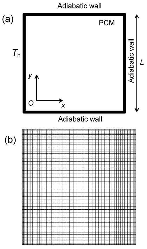
The schematic of the cavity configuration and the coordinate system employed in the present study are shown in Fig. 1a. The physical model under consideration is a 2D square cavity with side length of 1 cm filled with Cu-paraffin nanofluid as PCM. The nanofluid, including nanoparticles and base fluid as continuous media, is Newtonian, incompressible and assumed to be in thermal equilibrium. A no-slip condition between the media is imposed. The thermophysical properties are considered to be constant except the density, which is modeled by Boussinesq approximation to account for the thermal buoyancy (Table 1). In Table 1, the properties ρ, μ, Cp, k, α, β, L, Pr and Φ denote density, dynamic viscosity, specific heat at constant pressure, thermal conductivity, thermal diffusivity, thermal expansion, latent heat of fusion, Prandtl number and volume fraction of nanoparticles, respectively. The left wall is maintained at a constant temperature above the melting temperature of the mixture whereas the other three walls are assumed to be thermally insulated. The temperature difference between the hot wall temperature and the melting temperature of the mixture is 10 °C. With respect to these assumptions, the governing equations can be written as follows:
continuity equation
,
momentum equations
,
,
energy equation
,
where t is the time, u and v are the velocity components respectively in the x and y directions, p denotes the pressure, T is the temperature, S represents the source term, g is the acceleration of gravity, and h is the specific enthalpy. In addition, the subscripts ref, nf, 0, h and d denote reference value, nanofluid, stagnant, specific enthalpy and thermal dispersion, respectively.
Table 1
Thermo-physical properties of the nanofluid and its constituents
Nanofluid and its constituents
ρ (kg/m3)
μ (Pa·s)
Cp (J/(kg·K))
k (W/(m·K))
α (m2/s)
β (1/K)
L (J/kg)
Pr
Fusion point (°C)
Cu nano-particle
8954.00
383.00
400
1.17×10⁻⁴
Base fluid, Φ=0.000
780.00
2.870×10⁻³
2310.00
0.1505
8.35×10⁻⁸
9.10×10⁻⁴
228 900
44.06
18.3
Nanofluid, Φ=0.025
984.35
3.057×10⁻³
1871.78
0.1620
8.79×10⁻⁸
7.06×10⁻⁴
176 846
35.31
18.3
Nanofluid, Φ=0.050
1188.70
3.260×10⁻³
1584.00
0.1742
9.25×10⁻⁸
5.70×10⁻⁴
142 689
29.66
18.3
Fig.1 Physical configuration and coordinate system (a) and typical computational grid (b)
The density of the nanofluid is written as
,
where the subscripts f and s denote base fluid and solid, respectively. The heat capacities of the nano-fluid and part of the Boussinesq term can be expressed as
,
.
The viscosity of the nanofluid containing a diluted suspension of fine spherical particles can be written as
.
The effective thermal conductivity keff is given by
,
where
.
Here, D is an empirically-determined constant and dp is the nanoparticle diameter.
The specific enthalpy h in Eq. (4) is the sum of the sensible enthalpy , and the enthalpy increment due to the phase-change fLnf. Here, f is the liquid fraction during the phase change, which varies between zero for solid and one for liquid and is given by
where the subscript l stands for liquid. The source terms of the momentum and energy equations are expressed as
,
where causes the gradual decrease in the velocities from a finite value in the liquid to zero in the full solid in the computational cells that are changing phase. Here ε=0.001, is a small computational constant used to avoid division by zero, and C is a constant reflecting the morphology of the melting front. This constant is usually large and lies in the interval [104–107]. In the current study C is set to 1.6×10⁶.
3. Numerical procedure
A home-generated FORTRAN code based on the finite volume method on collocated body-fitted grids using the semi-implicit method for pressure-linked equations (SIMPLE) algorithm was developed to solve the governing equations. The convective terms are discretized using a second order upwind scheme, implemented using the deferred correction approach. Central differences are used for the viscous terms and a fully implicit scheme is utilized for marching in time. The discretized equations were solved using strongly implicit procedure (SIP). The enthalpy-porosity (Voller and Prakash, 1987; Dutta et al., 2008) method was applied to simulate the NEPCM melting in the cavity. In this method, the fraction of each cell volume which is in liquid phase is set equal to the porosity in that cell.
The liquid fraction is computed at each iteration, based on the enthalpy balance. Due to the steep gradient of the flow properties near the cavity walls, a finer grid has to be used in these regions to obtain accurate numerical solutions. Therefore, the grid becomes finer towards the walls of the cavity (Fig. 1b).
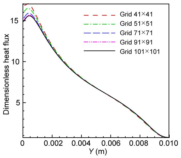
To test the mesh dependency of the solution, simulations were conducted using five different grid sizes of 41×41, 51×51, 71×71, 91×91 and 101×101. The associated results are depicted in Fig. 2. As there is a negligible difference between the results related to the last two grid sizes, in all the simulations carried out in the present work the grid size of 91×91 is employed.
Fig.2 Effects of grid size on the variation of dimensionless heat flux at t=500 s during melting in a cavity with a side length of 1 cm
4. Validation of the numerical procedure
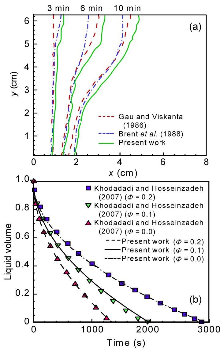
To verify the validity and accuracy of the present study, the results were compared with other available numerical and experimental results. To evaluate the ability of the enthalpy-porosity method to model the phase change process, the experimental and numerical results from melting gallium in a rectangular cavity obtained by Gau et al. (1986) and Brent et al. (1988), respectively, were compared with the present results. The top and bottom walls are assumed to be thermally insulated and the right and left walls are kept at constant low (cooling) and high (heating) temperatures, respectively. Fig. 3a displays the results of the melting front progression with time in the present study and those obtained by Gau et al. (1986) and Brent et al. (1988). There is acceptable agreement between the results. Another validation was performed by comparison of the present results of NEPCM solidification with those of Khodadadi et al. (2007). A good agreement between the results can be observed (Fig. 3b).
Fig.3 Melting phase front progression with time in comparison of the present results with those of Gau and Viskanta (1986) and Brent et al. (1988) (a); Change in the liquid volume fraction with time in comparison of the present results with those of Khodadadi and Hosseinzadeh (2007) (b)
5. Results and discussion
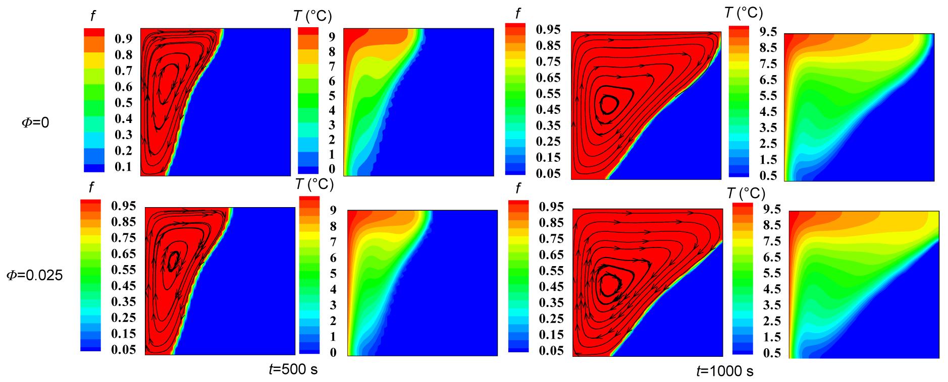
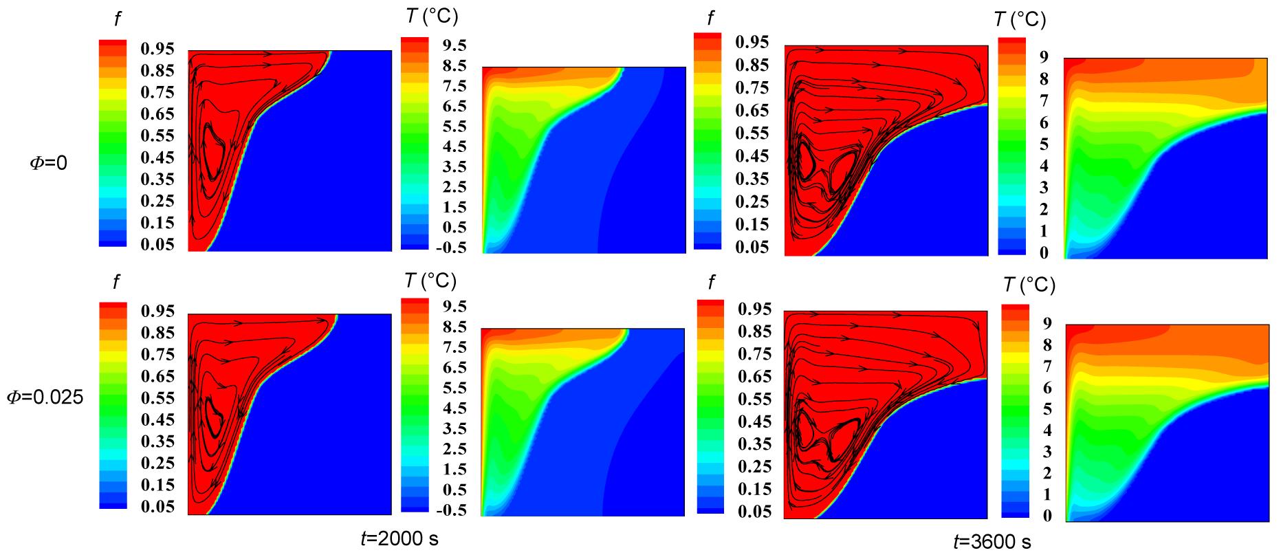
Figs. 4 and 5 show the results of streamlines (phase front) and isotherms of the nanofluid at various melting times for different volume fractions of nanoparticles in the cavities with side lengths of 1 cm or 3 cm, respectively. Note that the values of the temperature contours are computed based on the temperature difference between the melting temperature and the nanofluid temperature. The patterns of isotherms and streamlines change with the increase in the volume fraction of the nanoparticles and time. Since the temperature of the hot wall is maintained above the melting temperature of the nanofluid, the nanofluid starts melting on the left wall. The melting occurs faster in upper region of the cavity compared to the lower region due to the higher temperature in the upper section (Figs. 4 and 5).
Fig.4 Streamlines and isotherms in the melting zone using various nanoparticle volume fractions of Cu for different times in a cavity with a side length of 1 cm The red and blue colors used in the streamlines are indicative of liquid and solid phases, respectively (Note: for interpretation of the references to color in this figure legend, the reader is referred to the web version of this article)
Fig.5 Streamlines and isotherms in the melting zone using various nanoparticle volume fractions of Cu for different times in a cavity with a side length of 3 cm The red and blue colors used in the streamlines are indicative of liquid and solid phases, respectively (Note: for interpretation of the references to color in this figure legend, the reader is referred to the web version of this article)
At the beginning of the melting process, isotherms are parallel near the hot wall implying that the domination of the conduction mechanism and convection mode cannot play a significant role in heat transfer. This is because of the limited range of motion as a result of the resistance imposed by viscose forces. This situation is thermally unstable and therefore, as time goes by, the phase front moves from the hot wall (left) towards the right wall and the liquid phase occupies a major part of the cavity, expediting the melting process and advection in the liquid phase. So the natural convection flow occurs near the left wall and the flow moves upwards in close proximity to the hot wall, which has a significant effect on the thermal field and consequently the speed and shape of the travelling phase front. At lower times the liquid-solid interface is more flat compared to that at higher times when it is more distorted. The advancement of the liquid-solid interface where the hot fluid moves upwards is more pronounced than that near the right wall where the cold nanofluid descends.
After a long enough time, thermal stratification and departure of the isotherms from being parallel or distortion of isotherms occurs, the convection mode becomes more dominant and a thermal boundary layer develops near the hot wall. Further from the hot wall, the flow is not much affected by thermal boundary layers and hence the temperature gradient is not severe. As the volume fraction of nanoparticle increases, the isotherms in this region become almost horizontal which restricts the vertical motion of the flow. By adding nanoparticles to the base fluid the heat transfer rate is enhanced because of the increase in the thermal conductivity of the nanofluid. An increase in the nanoparticle volume fraction results in heat transfer enhancement and consequently a higher rate of progression of the phase front at the same time (Figs. 4 and 5). However, the volume occupied by pure fluid is diminished by the increasing volume fraction of the nanoparticles which in turn decreases the amount of energy stored by the nanofluid.
The variation in temperature distribution and vertical velocity of a nanofluid for various volume fractions of nanoparticles along the central line of a cavity with a side length of 1 cm at t=1000 s are depicted in Figs. 6a and 6b, respectively. The temperature is found to increase with the increasing volume fraction of the nanoparticles, causing an enhanced heat transfer rate, especially via a conduction mechanism.
Fig.6 Temperature distribution (a) and vertical velocity distribution (b) along the central line of a cavity with a side length of 1 cm at t=1000 s using various nanoparticle volume fractions
The increase in the volume fraction of nanoparticles has two major effects. The first is increased thermal conductivity leading to a higher rate of heat transfer, and the second is increased viscosity of the nanofluid resulting in a decrease in the velocity field.
A better understanding of the effect of nanoparticle addition to a base fluid on the rate of heat transfer through convection and conduction modes requires an accurate study of dimensionless heat flux on the hot wall. Fig. 7 shows the variation in dimensionless heat flux along the hot wall of a cavity with a side length of 1 cm for various volume fractions of nanoparticles at different times. This parameter can be considered as a local dimensionless temperature gradient indicating the ratio of conductive to convective resistance. As the volume fraction of nanoparticle increases, the dimensionless heat flux decreases in spite of the increasing heat transfer rate. The reduction in the local dimensionless temperature gradient on the hot wall and, conversely, the increase in the thermal conductivity of the nanofluid resulting in decreased conductive thermal resistance, means that increasing the volume fraction of the nanoparticles can lead to a decrease in convective thermal resistance. But the rate of decrease in conductive thermal resistance is much higher than that in convective thermal resistance.
Fig.7 Dimensionless heat flux distribution along the hot wall of a cavity with a side length of 1 cm using various nanoparticle volume fractions at t=500 s (a), 1000 s (b) and 1500 s (c)
The dimensionless heat flux on the hot wall decreases with time and with progression of the phase front, owing to reducing thermal conductive strength. This can be considered a consequence of uniform temperature distribution with time (t=1500 s).
It can be concluded that the uniformity of temperature distribution for higher volume fractions of nanoparticles occurs faster over time. The most pronounced difference between the dimensionless heat flux curves is associated with the time t=1500 s. This is due to the higher heat transfer rate in the cavity for the higher volume fractions of the nanoparticles.
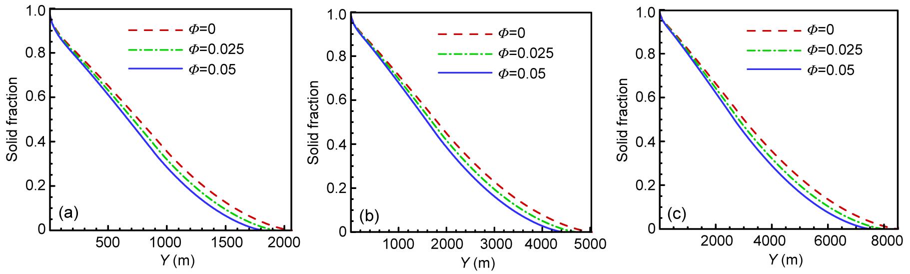
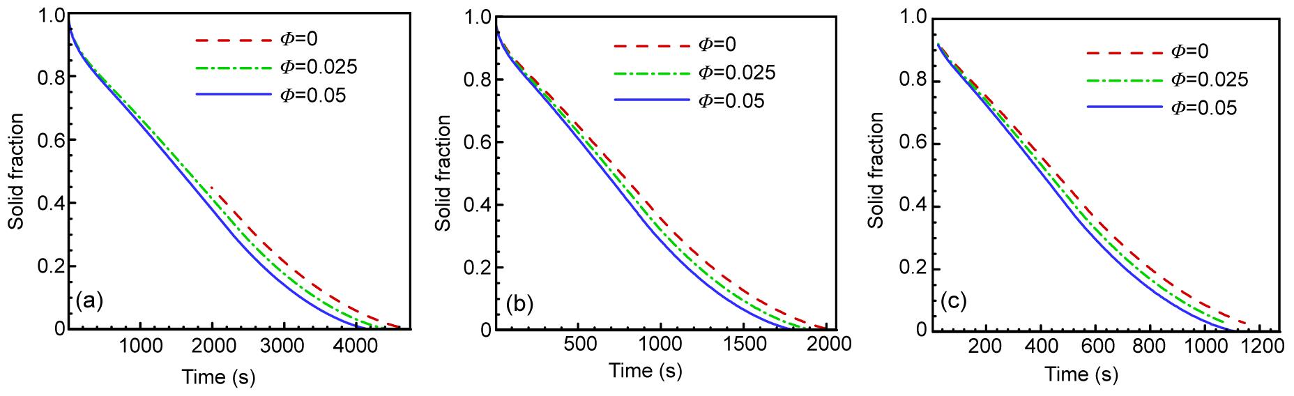
To study the effect of nanoparticle addition on the length of the melting process, which is an important factor in the design of latent thermal energy storage systems, the variation in the solid fraction over time for various volume fractions of nanoparticles in three cavities of different sizes (1 cm, 2 cm and 3 cm) was investigated (Fig. 8). As the presence of nanoparticles in the base fluid leads to higher thermal conductivity as well as lower latent heat, it has an effective role in reducing the length of the melting process. By adding a nanoparticle volume fraction of 5%, the total melting time in a cavity with a side length of 1 cm decreases by about 15% compared to pure fluid. However, the effect of nanoparticle dispersion on the reduction in melting time of NEPCM is more pronounced for the larger cavities. Fig. 9 indicates the effect of a temperature difference (between the hot wall temperature and the melting temperature) of 5 °C, 10 °C or 15 °C on the melting time for different volume fractions in a cavity of 1 cm.
Fig.8 Variation in the solid fraction with time using various nanoparticle volume fractions in cavities with side lengths of 1 cm (a), 2 cm (b) and 3 cm (c)
Fig.9 Variation in the solid fraction with time using different nanoparticle volume fractions in a cavity with a side length of 1 cm for temperature differences of 5 °C (a), 10 °C (b) and 15 °C (c)
The addition of nanoparticles leads to a decrease in melting time in all cases. Moreover, the effect of nanoparticles on the decrease in melting time of NEPCM becomes more significant as the temperature difference between the melting temperature and the hot wall temperature increases. For instance, the time to complete melting of an NEPCM with Φ=0.05 for a temperature difference of 15 °C is about 1050 s, com-pared with 3800 s for a temperature difference of 5 °C.
6. Conclusions
This paper presents a comprehensive numerical investigation of melting in a 2D square cavity filled with NEPCM. The effects of nanoparticle dispersion during melting with various volume fractions of Cu are studied numerically using a pressure based finite volume method with an enthalpy porosity technique. The main results are as follows:
At the beginning of the melting process, conductive heat transfer dominates and isotherms are parallel near the hot wall. Buoyancy-driven convection is strengthened and melting occurs faster in the top region of the cavity.
The solid fraction decreases approximately linearly with time, although the decrease rate will be attenuated at the end of the melting process.
Dispersion of nanoparticles in a PCM results in an increase in thermal conductivity and an enhanced heat transfer rate, and consequently decreases the melting time.
The rate of heat transfer is increased by increasing the nanoparticle volume fraction. However, the volume occupied by pure fluid is diminished by increasing the volume fraction of nanoparticles which in turn decreases the amount of energy stored by the nanofluid.
The effect of nanoparticle dispersion on the reduction in the melting time of NEPCM is more pronounced for larger cavities.
The influence of nanoparticles on the decrease in melting time of NEPCM becomes more significant as the temperature difference between the melting temperature and the hot wall temperature increases.
The fluid flow and the shape of the phase front depend on the liquid layer thickness and the nanoparticle volume fraction during the progress of melting.
Using a proper suspension of nanoparticles in conventional PCMs has great potential for improving traditional energy storage systems.
Acknowledgements
The authors would like to acknowledge the Delvar Afzar Industrial Gases Co., Iran for providing financial support for this research.
References
[1] Arasu, A.V., Mujumdar, A.S., 2012. Numerical study on melting of paraffin wax with Al2O3 in a square enclosure. International Communications in Heat and Mass Transfer, 39(1):8-16.
[2] Brent, A.D., Voller, V.R., Reid, K.J., 1988. Enthalpy-porosity technique for modeling convection-diffusion phase change: application to the melting of a pure metal. Numerical Heat Transfer, 13(3):297-318.
[3] Cabeza, L.F., Casteii, A., Barreneche, C., de Gracia, A., Fernndez, A.I., 2011. Materials used as PCM in thermal energy storage in buildings: A review. Renewable and Sustainable Energy Reviews, 15(3):1675-1695.
[4] Choi, U.S., 1995. Enhancing Thermal Conductivity of Fluids with Nanoparticles. Developments and Application of Non-Newtonian Flows. ASME,New York, USA :99-105.
[5] Corcione, M., 2010. Heat transfer features of buoyancy-driven nanofluids inside rectangular enclosures differentially heated at the sidewalls. International Journal of Thermal Sciences, 49(9):1536-1546.
[6] Darzi, A.R., Farhadi, M., Sedighi, K., 2012. Numerical study of melting inside concentric and eccentric horizontal annulus. Applied Mathematical Modelling, 36(9):4080-4086.
[7] Dutta, R., Atta, A., Dutta, T.K., 2008. Experimental and numerical study of heat transfer in horizontal concentric annulus containing phase change material. The Canadian Journal of Chemical Engineering, 86(4):700-710.
[8] Fang, X., Zhang, Z., Chen, Z., 2008. Study on preparation of montmorillonite-based composite phase change materials and their applications in thermal storage building materials. Energy Conversion and Management, 49(4):718-723.
[9] Faraji, M., El Qarnia, H., 2010. Numerical study of melting in an enclosure with discrete protruding heat sources. Applied Mathematical Modelling, 34(5):1258-1275.
[10] Gau, C., Viskanta, R., 1986. Melting and solidification of a pure metal on a vertical wall. Journal of Heat Transfer, 108(1):174-181.
[11] Gong, Z.X., Mujumdar, A.S., 1996. Enhancement of energy charge-discharge rates in composite slabs of different phase change materials. International Journal of Heat and Mass Transfer, 39(4):725-733.
[12] Ho, C.J., Chen, M.W., Li, Z.W., 2008. Numerical simulation of natural convection of nanofluid a square enclosure: Effects due to uncertainties of viscosity and thermal conductivity. International Journal of Heat and Mass Transfer, 51(17-18):4506-4516.
[13] Ho, C.J., Gao, J.Y., 2009. Preparation and thermophysical properties of nanoparticle-in-paraffin emulsion as phase change material. International Communications in Heat and Mass Transfer, 36(5):467-470.
[14] Ho, C.J., Liu, W.K., Chang, Y.S., Lin, C.C., 2010. Numerical natural convection heat transfer of alumina-water nanofluid in vertical square enclosures: An experimental study. International Journal of Thermal Sciences, 49(8):1345-1353.
[15] Hosseinizadeh, S.F., Rabienataj Darzi, A.A., Tan, F.L., 2012. Numerical investigations of unconstrained melting of nano-enhanced phase change material (NEPCM) inside a spherical container. International Journal of Thermal Sciences, 51:77-83.
[16] Kashani, S., Ranjbar, A.A., Abdollahzadeh, M., Sebti, S.S., 2012. Solidification of nano-enhanced phase change material (NEPCM) in a wavy cavity. Heat and Mass Transfer, 48(7):1155-1166.
[17] Khillarkar, D.B., Gong, Z.X., Mujumdar, A.S., 2000. Melting of a phase change material in concentric horizontal annuli of arbitrary cross-section. Applied Thermal Engineering, 20(10):893-912.
[18] Khodadadi, J.M., Hosseinizadeh, S.F., 2007. Nanoparticle-enhanced phase change materials (NEPCM) with great potential for improved thermal energy storage. International Communications in Heat and Mass Transfer, 34(5):534-543.
[19] Ng, K.W., Gong, Z.X., Mujumdar, A.S., 1998. Heat transfer in free convection-dominated melting of a phase change material in a horizontal annulus. International Communications in Heat and Mass Transfer, 25(5):631-640.
[20] Ranjbar, A.A., Kashani, S., Hosseinizadeh, S.F., Ghanbarpour, M., 2011. Numerical heat transfer studies of a latent heat storage system containing nano-enhanced phase change material. Thermal Science, 15(1):169-181.
[21] Sari, A., Karaipekli, A., 2009. Preparation, thermal properties and thermal reliability of palmitic acid/expanded graphite composite as form-stable PCM for thermal energy storage. Solar Energy Materials and Solar Cells, 93(5):571-576.
[22] Sebti, S.S., Khalilarya, S.H., Mirzaee, I., Hosseinizadeh, S.F., Kashani, S., Abdollahzadeh, M., 2011. A numerical investigation of solidification in horizontal concentric annuli filled with nano-enhanced phase change material (NEPCM). World Applied Sciences Journal, 13(1):09-15.
[23] Sharifi, N., Bergman, T.L., Faghri, A., 2011. Enhancement of PCM melting in enclosures with horizontally-finned internal surfaces. International Journal of Heat and Mass Transfer, 54(19-20):4182-4192.
[24] Sharma, A., Tyagi, V.V., Chen, C.R., Buddhi, D., 2009. Review on thermal energy storage with phase change materials and applications. Renewable and Sustainable Energy Reviews, 13(2):318-345.
[25] Shatikian, V., Ziskind, G., Letan, R., 2005. Numerical investigation of a PCM-based heat sink with internal fins. International Journal of Heat and Mass Transfer, 48(17):3689-3706.
[26] Tan, F.L., Hosseinizadeh, S.F., Khodadadi, J.M., Fan, L., 2009. Experimental and computational study of constrained melting of phase change materials (PCM) inside a spherical capsule. International Journal of Heat and Mass Transfer, 52(15-16):3464-3472.
[27] Tay, N.H.S., Bruno, F., Belusko, M., 2012. Experimental validation of a CFD model for tubes in a phase change thermal energy storage system. International Journal of Heat and Mass Transfer, 55(4):574-585.
[28] Voller, V.R., Prakash, C., 1987. A fixed-grid numerical modeling methodology for convection-diffusion mushy region phase-change problems. International Journal of Heat and Mass Transfer, 30(8):1709-1719.
[29] Wang, N., Zhang, X.R., Zhu, D.S., Gao, J.W., 2012. The investigation of thermal conductivity and energy storage properties of graphite/paraffin composites. Journal of Thermal Analysis and Calorimetry, 107(3):949-954.
[30] Zalba, B., Marn, J.M., Cabeza, L.F., Mehling, H., 2003. Review on thermal energy storage with phase change: materials, heat transfer analysis and applications. Applied Thermal Engineering, 23(3):251-283.
Open peer comments: Debate/Discuss/Question/Opinion


Open peer comments: Debate/Discuss/Question/Opinion
<1>