ZHU Z.Q., SHI Y.F., HOWE D.. Influence of DSP controller on performance of a permanent magnet brushless AC drive in flux-weakening mode[J]. Journal of Zhejiang University Science A, 2005, 6(2): 83-89.
@article{title="Influence of DSP controller on performance of a permanent magnet brushless AC drive in flux-weakening mode", author="ZHU Z.Q., SHI Y.F., HOWE D.", journal="Journal of Zhejiang University Science A", volume="6", number="2", pages="83-89", year="2005", publisher="Zhejiang University Press & Springer", doi="10.1631/jzus.2005.A0083" }
%0 Journal Article %T Influence of DSP controller on performance of a permanent magnet brushless AC drive in flux-weakening mode %A ZHU Z.Q. %A SHI Y.F. %A HOWE D. %J Journal of Zhejiang University SCIENCE A %V 6 %N 2 %P 83-89 %@ 1673-565X %D 2005 %I Zhejiang University Press & Springer %DOI 10.1631/jzus.2005.A0083
TY - JOUR T1 - Influence of DSP controller on performance of a permanent magnet brushless AC drive in flux-weakening mode A1 - ZHU Z.Q. A1 - SHI Y.F. A1 - HOWE D. J0 - Journal of Zhejiang University Science A VL - 6 IS - 2 SP - 83 EP - 89 %@ 1673-565X Y1 - 2005 PB - Zhejiang University Press & Springer ER - DOI - 10.1631/jzus.2005.A0083
Abstract: The flux-weakening performance of a permanent magnet brushless AC drive was investigated using both floating-point and fixed-point DSP controllers. A significant current oscillation was observed when the drive was operated at high-speed in the flux-weakening mode with the fixed-point DSP. The investigation showed that this was due to the on-line compensation of the winding resistance voltage drop and quantisation errors associated with the fixed-point architecture of the DSP. A simple look-up table scheme is proposed to eliminate the oscillation and to achieve extended flux-weakening capability.
Darkslateblue:Affiliate; Royal Blue:Author; Turquoise:Article
Article Content
. INTRODUCTION
For applications such as traction and spindle drives (Morimoto et al., 1996; Kim and Sul, 1997; Sudhoff et al., 1995) permanent magnet brushless AC (BLAC) motors are required to operate in both constant torque and flux-weakening modes. The performance of a BLAC drive with a floating-point (TMS320C31) (Shi et al., 2002), and a fixed-point (TMS320F240 − having 16-bit word-length) DSP-
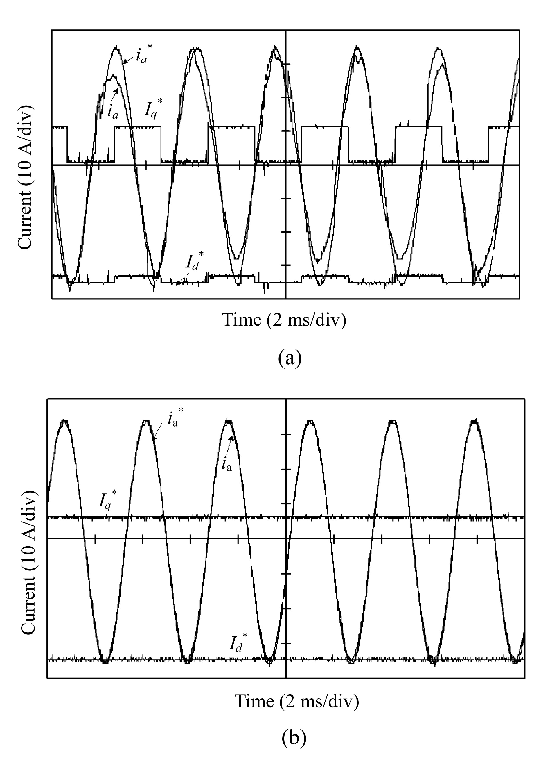
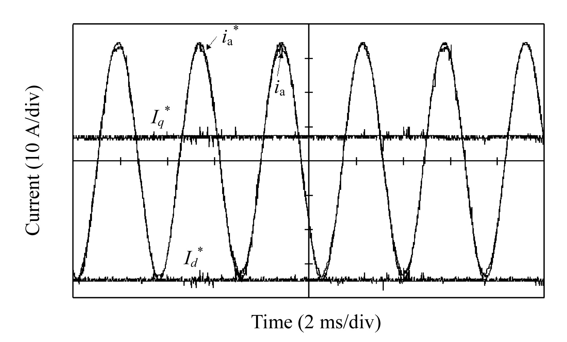
based controller was investigated. Significant current oscillation was observed with the fixed-point DSP-based controller when the drive was operated in the flux-weakening mode and incorporated on-line compensation of the winding resistance voltage drop. By way of example, Fig.1a shows commanded d- and q-axis currents and (asterisks designating commanded values) which result with the fixed-point DSP-based control system, for the BLAC motor whose parameters are given in Table 1 and whose back-emf waveforms are shown in Fig.2 (see the next page). It can be seen that and vary between upper and lower values about every 2 ms. Consequently, the commanded phase current derived from and via a dq-to-abc transformation, departs from a sinusoid, whilst the amplitude of the actual phase current ia also varies. In contrast, with the floating-point DSP-based control system and are constant and, thus, ia is sinusoidally time-varying and has a constant amplitude, as shown in Fig.1b, the control algorithms for both systems being identical. The authors investigated the origin of the observed current oscillation and proposed a simple and effective solution for the problem.
Fig.1 Current waveforms for BLAC drive in flux-weakening mode (2900 rpm) (a) Fixed-point DSP; (b) Floating-point DSP
Fig.2 Open-circuit back-emfs of BLAC motor (1000 rpm)
Table 1
Parameters of BLAC motor
R
Phase winding resistance (()
0.15
Ld=Lq
d, q-axis inductance (mH)
0.40
p
Number of pole-pairs
6
(m
Open-circuit flux-linkage (peak) (Wb)
0.0179
Udc
dc-link voltage (V)
21
Imax
Maximum armature current (A)
35
. INFLUENCE OF WINDING RESISTANCE ON FLUX-WEAKENING PERFORMANCE
The steady-state d-q axis voltage equations for a BLAC motor are: where Ud, Uq, Id, Iq, Ld, Lq are the d- and q-axis voltages, currents, and inductances, respectively; R is the phase winding resistance; ω is the synchronous electrical angular velocity; and ψm is the maximum flux-linkage per phase due to the permanent magnets. The peak phase voltage and current, Ua and Ia, which are limited by the inverter, are:
The torque and the power are given by:
and where p is the number of pole-pairs; Imax is the maximum phase current; and Umax is the maximum inverter voltage, which can be estimated from the dc-link voltage Udc, viz. Umax=2Udc/π (Sudhoff et al., 1995).
In order to simplify the control algorithm, the winding resistance R is first neglected in deriving the relationship between d-q axis currents (However, the resistance voltage drop will subsequently be compensated for). Therefore,
Thus, in the constant torque mode (i.e. below the base speed), when maximum torque per ampere control is used (Morimoto et al., 1996):
In the flux-weakening mode, the optimal d- and q-axis current profiles are derived from the voltage and current constraints of the inverter: for Ld<Lq
Since and assuming a BLAC motor with a surface-mounted magnet rotor, for which Ld=Lq, the optimal d-axis current can be expressed as a function of the q-axis current Iq from Eq.(7):
It should be noted that if the winding resistance is accounted for, the expression for the optimal current profiles is much more complicated due to mutual coupling between the d- and q-axis currents. Therefore, in many studies the winding resistance is simply neglected (Morimoto et al., 1996; Kim and Sul, 1997). However, this compromises the performance, and is only appropriate for relatively high power machines which have relatively low winding resistance. For small motors, however, the influence of the winding resistance can be very significant. For example, for the motor whose parameters are given in Table 1, the maximum resistive voltage drop is ∼40% of the maximum terminal voltage, i.e.
It is desirable, therefore, to compensate for the effect of the winding resistance voltage drop so as to improve the performance, particularly in the flux-weakening mode.
In (Sudhoff et al., 1995), a simple ‘fixed R compensation’ technique was employed which simply subtracted the estimated maximum voltage drop across the winding resistance from the supply voltage, i.e.:
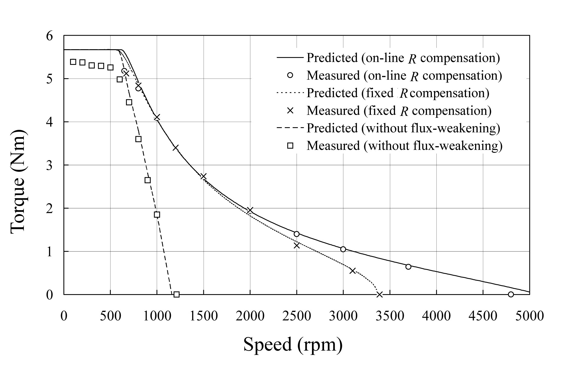
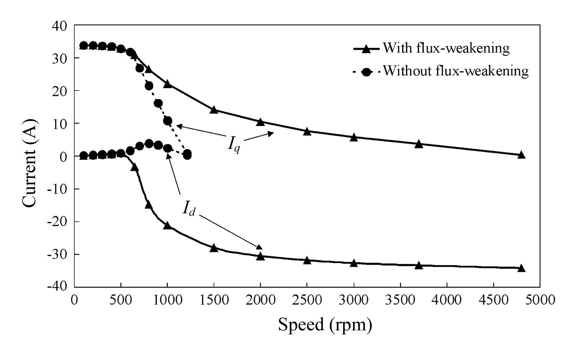
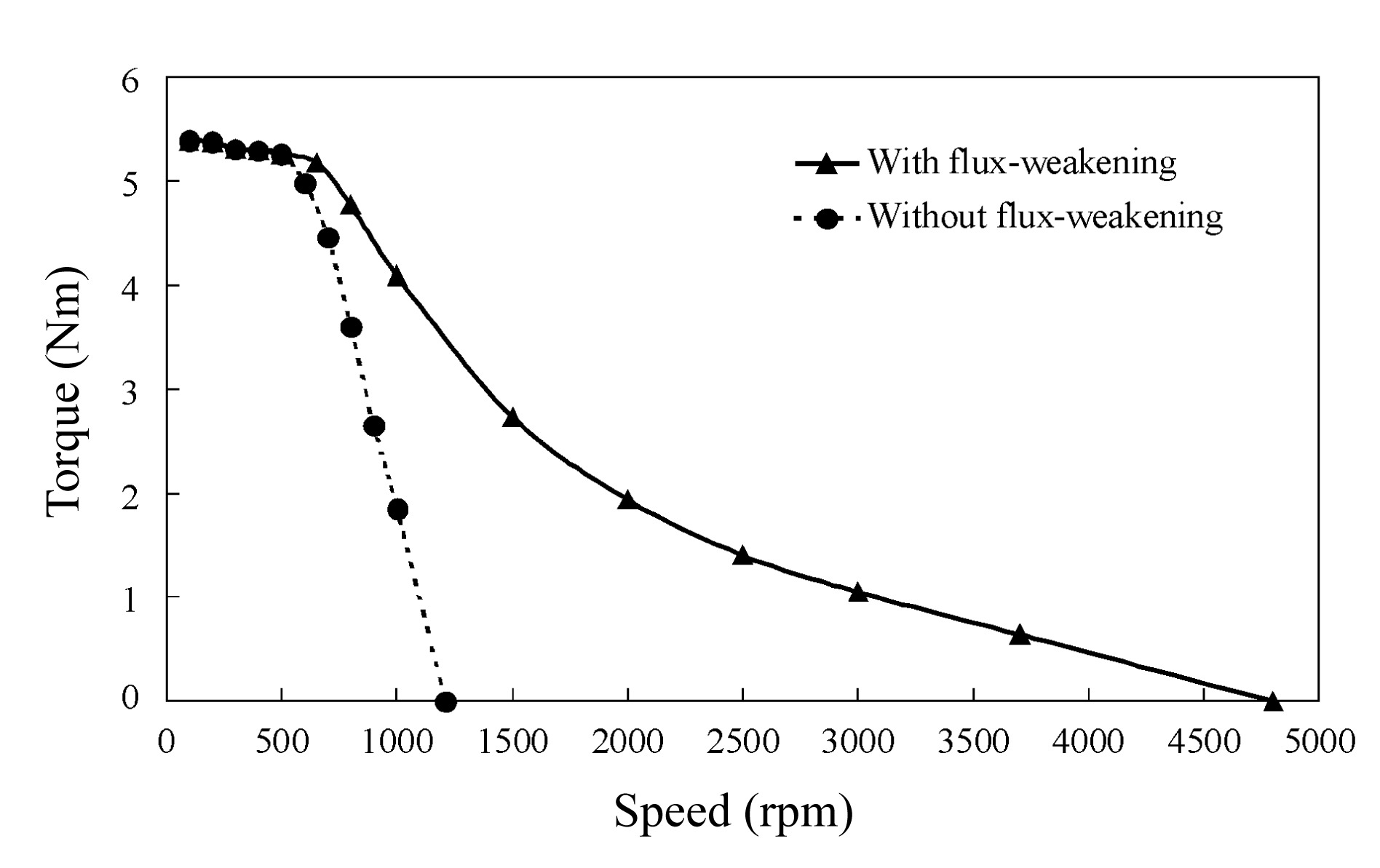
However, whilst this technique is easy to implement and improves the performance, most notably around the base-speed, it over-compensates for the effect of the winding resistance in the flux-weakening range, when the power factor decreases with increasing speed (Shi et al., 2002), and, thereby, compromises the achievable performance, as can be seen from Fig.3, which shows the measured flux-weakening performance of the BLAC motor whose parameters are given in Table 1.
Fig.3 Flux-weakening performance using floating-point DSP based controller
In order to improve the performance over the entire speed range, a feed-forward ‘on-line R compensation’ technique is proposed to compensate for the effect of the winding resistance voltage drop. Thus, from Eqs.(1) and (2), the effective terminal voltage , excluding the winding resistance voltage drop, can be derived as:
Hence,
Thus, the maximum terminal voltage can be determined from the predicted d- and q-axis currents on the previous control cycle in order to compensate for the influence of the winding resistance voltage drop, i.e.:
By way of example, Fig.3 also includes the measured flux-weakening performance when on-line feed-forward resistance voltage drop compensation is employed. As can be seen, the high-speed performance is improved significantly. It is also worth mentioning that, for this particular motor, when the resistance voltage drop is neglected altogether the performance is essentially the same as that which results without flux-weakening control.
. DRIVE SYSTEM
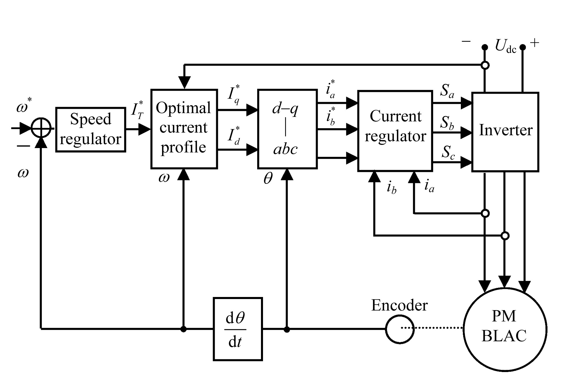
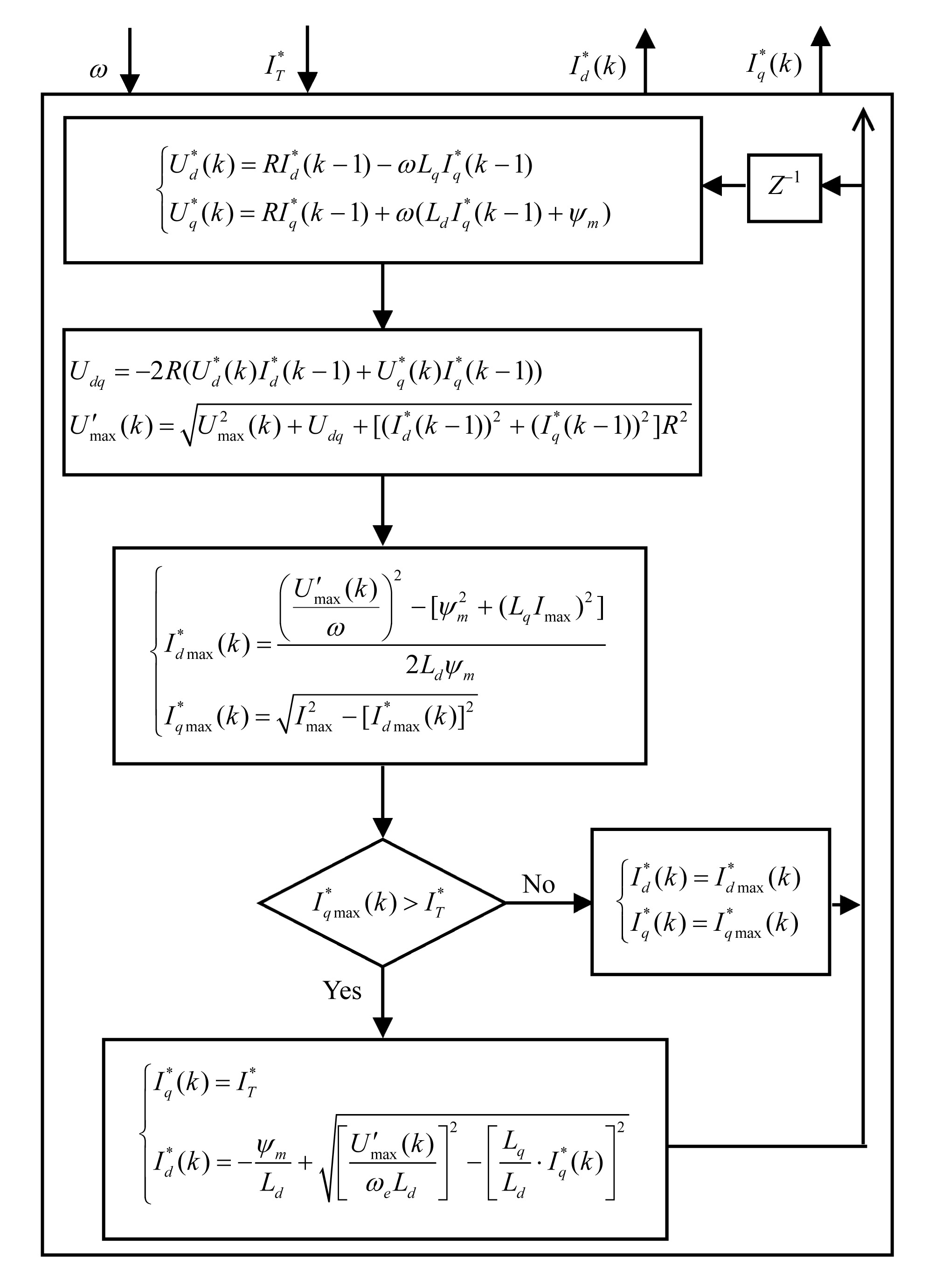
Fig.4 shows a schematic of the vector-controlled BLAC motor drive. The torque and airgap flux are varied by controlling the commanded current components and , which are transformed to commanded phase currents , and according to the instantaneous rotor position θ, which is obtained from an encoder. A hysteresis current-controlled inverter provides high accuracy current control. The current command , which is determined from the PI-type speed regulator, is decomposed into d- and q-axis components, and , respectively, according to the optimal current profiles for maximum torque, Eqs.(7) and (8). A flow-chart of the flux-weakening control algorithm which incorporates on-line resistance voltage drop compensation is shown in Fig.5.
Fig.4 Schematic of vector-controlled drive system
Fig.5 Flow-chart of flux-weakening control algorithm
The foregoing control strategy has been implemented on both floating-point (TMS320C31) and fixed-point (TMS320F240) DSPs. However, as mentioned in the introduction, significant current oscillations were observed when the motor whose parameters are given in Table 1 was operated in the flux-weakening mode with the fixed-point DSP-based controller. This will be investigated further by both simulations and experiments in the sections which follow.
. PERFORMANCE WITH FIXED-POINT AND FLOATING-POINT DSP CONTROLLERS
In a fixed-point DSP all the inputs, outputs and intermediate results are represented as fixed-point numbers with a given word-length (Texas Instruments, 1999). In order to achieve the highest possible accuracy, a per-unit model is utilised, so that the parameters remain within a narrow numerical range which is suited to the fixed-point format. Therefore, each quantity in the control algorithm is expressed relative to a reference value. Further, considering the dynamic range, precision and processing capability of the TMS320C240 DSP, the numerical format Q(4,12) is employed, in which the last 12 bits are allocated to the fractional portion and the first 4 bits to the integer portion of a real number. Nevertheless, the inherent constraints of the fixed-point architecture lead to finite numerical precision in the arithmetic computations (Wong, 1990; Proakis and Manolakis, 1996), such as:
1. Quantisation errors in the parameters: The relative accuracy of the Q(4,12) format is ∼2−12≈0.0244%. Thus, each quantisation step in the current can be ∼8.5 mA for a rated current of 35 A.
2. Truncation, round-off, and overflow in operations. Again, one bit of truncation in the integer for the current is equivalent to an error in the current of ∼8.5 mA.
In addition, quantisation errors due to the finite numerical precision can accumulate in the on-going arithmetic operations, particularly in a recursive system (Proakis and Manolakis, 1996). As will be shown later, quantisation errors due to the fixed-point DSP architecture have significant influence on the flux-weakening performance of the drive.
As can be seen from Fig.5, the flux-weakening control algorithm which incorporates on-line resistance voltage drop compensation is recursive and inherently non-linear, the control-state of the last cycle being used to modify the outputs of the latest cycle, and involves one square-root function. Unfortunately, as with other recursive algorithms, calculation errors arise due to quantisation, which can accumulate during the iterative process (Proakis and Manolakis, 1996) and may result in divergence of the algorithm. The algorithm shown in Fig.5 has been simulated with the fixed-point DSP controller, the input signals, i.e. rotor speed ω and the current command , being set via the program. The outputs are the optimal d- and q-axis currents, and . Fig.6a shows the results obtained with the Q(4,12) format. It can be seen that at high speeds significant oscillations occur in the commanded d- and q-axis currents as the d-axis current approaches its maximum value.
Fig.6 Commanded d- and q-axis currents (a) Fixed-point DSP using Q(4,12) format; (b) Fixed-point DSP using Q(2,14) format; (c) Floating-point DSP
In the flux-weakening speed range, the change in the commanded values of Id and Iq for maximum power is initially relatively large, as seen in Fig.6, and quantization errors are much less than the magnitude of Id and Iq. Hence, their influence is negligible. However, as the maximum speed is approached, Id levels off while Iq still varies significantly. In other words, a small change in Id results in a significant change in Iq, as shown in Fig.7, which shows the calculated sensitivity, dIq/dId, i.e.
Fig.7 Sensitivity of Iq with respect to Id in flux-weakening range
Hence, when quantization errors become large, the system starts to oscillate (at ∼3000 rpm in the drive system under consideration).
Clearly, if more bits were employed to represent the parameters in the flux-weakening control algorithm, the current oscillations could be reduced. By way of example, with a Q(2,14) format, in which 14 bits are designated to the fractional part of a real number compared to 12 bits in the Q(4,12) format, the oscillations in the d- and q-axis currents reduce, as shown in Fig.6b. However, if the required numerical format to reduce the oscillations exceeds 16 bits, multiplication and addition operations would have to be performed as multi-byte operations in software, which would require more processor cycles and additional memory. However, high speed dynamic operation in the flux-weakening mode demands a fast current control cycle (<40 μs) and may preclude the use of multi-byte operations. Of course, the current oscillations can be eliminated by using a floating-point DSP, as shown in Fig.6c. However, a fixed-point DSP may be necessary from cost considerations. Therefore, it is proposed to employ optimal current profiles that are determined in advance from simulations and stored in a look-up table, linear interpolation being effective in eliminating the current oscillations, as shown in Fig.8.
Fig.8 Commanded d- and q-axis currents with fixed-point DSP and look-up table
. EXPERIMENTAL RESULTS
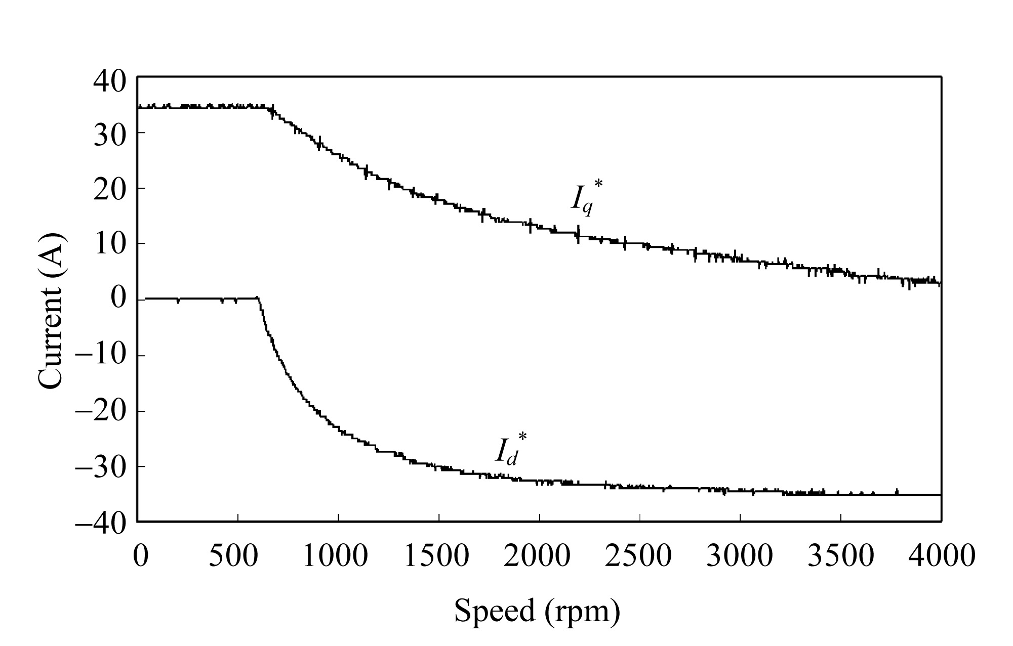
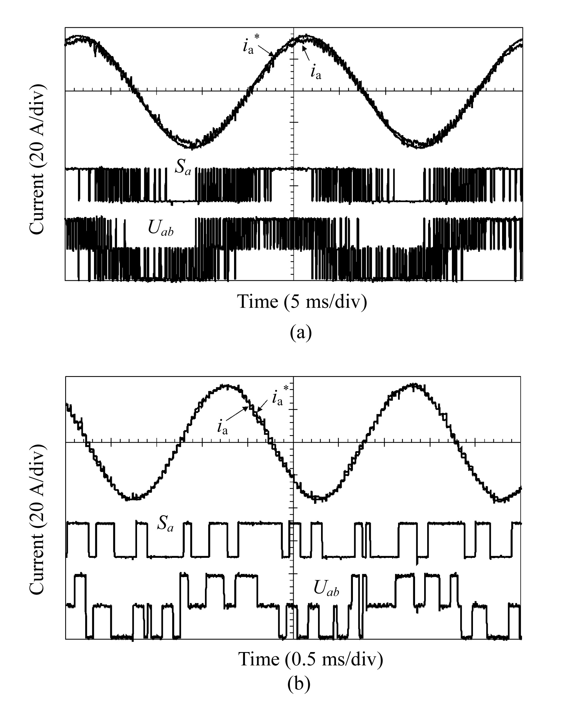
The proposed look-up table scheme has been implemented using the TMS320F240 fixed-point DSP and the Q(4,12) format, the resultant d- and q-axis current waveforms in the flux-weakening mode shown in Fig.9. As will be seen, the current oscillations are completely eliminated, and, by comparison with Fig.1a, it can be seen that the commanded d- and q-axis currents, and , are now constant in the steady-state and that the commanded phase current is sinusoidal. Fig.10 shows the measured variation of the d- and q-axis currents, Id and Iq, over the complete operating speed range. As can be seen, the oscillations, which previously occurred in Id and Iq at high speed, have been eliminated. Fig.11a shows the commanded and actual phase current waveforms when operating at 400 rpm in the constant torque mode, whilst Fig.11b shows the current waveforms at the maximum speed of 4800 rpm in the flux-weakening mode, which is about 8 times the base-speed and was previously impossible to achieve when a fixed-point DSP was employed due to the current oscillations. The achievable flux-weakening performance is shown in Fig.12. The measurements confirmed that the proposed look-up table scheme can result in good current tracking performance when a fixed-point DSP-based controller is employed.
Fig.9 Current waveforms with fixed-point DSP and look-up table (2900 rpm)
Fig.10 Measured d- and q-axis current profiles with fixed-point DSP and look-up table
Fig.11 Phase current, drive signal and line-to-line voltage (a) 400 rpm; (b) 4800 rpm
Fig.12 Torque-speed characteristics with fixed-point DSP and look-up table
. CONCLUSION
The cause of current oscillations in a permanent magnet brushless AC drive when a fixed-pint DSP-based controller is employed was investigated. By using a simple look-up table approach, the influence of quantisation errors which result with a fixed-point DSP and on-line resistance voltage drop compensation is eliminated and the flux-weakening performance is enhanced.
References
[1] Kim, J.M., Sul, S.K., 1997. Speed control of interior permanent magnet synchronous motor drive for the flux-weakening operation. IEEE Trans on Industry Applications, 33(1):43-48.
[2] Morimoto, S., Sanada, M., Takeda, Y., 1996. Inverter-driven Synchronous Motors for Constant Power. , IEEE Industry Application Magazine, 18-24. :18-24.
[3] Proakis, J.G., Manolakis, D.G., 1996. Digital Signal Processing: Principles, Algorithms, and Applications, 3rd Ed, Prentice-Hall,:
[4] Shi, Y.F., Zhu, Z.Q., Chen, Y.S., 2002. Influence of Winding Resistance on Flux-weakening Performance of A Permanent Magnet Brushless AC Drive. , Proc. Int. Conf. Power Electronics, Machines and Drives, IEE, 392-397. :392-397.
[5] Sudhoff, S.D., Corzine, K.A., Hegner, H.J., 1995. A flux-weakening strategy for current-regulated surface-mounted permanent-magnet machine drives. IEEE Trans on Energy Conversion, 10(3):431-437.
[6] Instruments, T.e.x.a.s., 1999. TMS320F/24x DSP Controllers CPU and Instruction Set Reference Guide. , (Rev. C),:
[7] Wong, P.W., 1990. Quantization noise, fixed-point multiplicative roundoff noise, and dithering. IEEE Trans on Signal Processing, 38(2):286-300.
Open peer comments: Debate/Discuss/Question/Opinion


Open peer comments: Debate/Discuss/Question/Opinion
<1>