Li Zhou, Zhi-yun Shen. Dynamic analysis of a high-speed train operating on a curved track with failed fasteners[J]. Journal of Zhejiang University Science A, 2013, 14(6): 447-458.
@article{title="Dynamic analysis of a high-speed train operating on a curved track with failed fasteners", author="Li Zhou, Zhi-yun Shen", journal="Journal of Zhejiang University Science A", volume="14", number="6", pages="447-458", year="2013", publisher="Zhejiang University Press & Springer", doi="10.1631/jzus.A1200321" }
%0 Journal Article %T Dynamic analysis of a high-speed train operating on a curved track with failed fasteners %A Li Zhou %A Zhi-yun Shen %J Journal of Zhejiang University SCIENCE A %V 14 %N 6 %P 447-458 %@ 1673-565X %D 2013 %I Zhejiang University Press & Springer %DOI 10.1631/jzus.A1200321
TY - JOUR T1 - Dynamic analysis of a high-speed train operating on a curved track with failed fasteners A1 - Li Zhou A1 - Zhi-yun Shen J0 - Journal of Zhejiang University Science A VL - 14 IS - 6 SP - 447 EP - 458 %@ 1673-565X Y1 - 2013 PB - Zhejiang University Press & Springer ER - DOI - 10.1631/jzus.A1200321
Abstract: A high-speed train-track coupling dynamic model is used to investigate the dynamic behavior of a high-speed train operating on a curved track with failed fasteners. The model considers a high-speed train consisting of eight vehicles coupled with a ballasted track. The vehicle is modeled as a multi-body system, and the rail is modeled with a Timoshenko beam resting on the discrete sleepers. The vehicle model considers the effect of the end connections of the neighboring vehicles on the dynamic behavior. The track model takes into account the lateral, vertical, and torsional deformations of the rails and the effect of the discrete sleeper support on the coupling dynamics of the vehicles and the track. The sleepers are assumed to move backward at a constant speed to simulate the vehicle running along the track at the same speed. The train model couples with the track model by using a Hertzian contact model for the wheel/rail normal force calculation, and the nonlinear creep theory by Shen et al. (1984) is used for wheel/rail tangent force calculation. In the analysis, a curved track of 7000-m radius with failed fasteners is selected, and the effects of train operational speed and the number of failed fasteners on the dynamic behaviors of the train and the track are investigated in detail. Furthermore, the wheel/Rail forces and derailment coefficient and the wheelset loading reduction are analyzed when the high-speed train passes over the curved track with the different number of continuously failed fasteners at different operational speeds. Through the detailed numerical analysis, it is found that the high-speed train can operate normally on the curved track of 7000-m radius at the speeds of 200 km/h to 350 km/h.
Darkslateblue:Affiliate; Royal Blue:Author; Turquoise:Article
Article Content
1. Introduction
Railway track support failure quite often takes place in service due to the non-uniform roadbed settlement and the fierce wheel/rail vibration at high frequencies, which may originate from non-homogeneities in the ballast and substrate or from out of the roundness of wheels and rail corrugation. Railway track support failure mainly includes the fastener fracture, sleeper fracture or sleeper suspension, slab fracture, ballasted bed collapse, etc. Augustin et al. (2003) found, in their experimental study on the settlement of a ballasted track, that up to 50% of all sleepers are more or less hanging. The track support failure results in railroad accidents of derailment. On Dec. 21, 1993, an unsupported track section (Fig. 1), caused a derailment of an SNCF TGV train at the Haute Picardie, France (Brabie, 2005). On Aug. 9, 1997, an Amtrak Southwest Chief train derailed on the east bound track near Kingman, Arizona, USA when crossing an unsupported bridge section (National Transportation Safety Board, 1999). On June 26, 1999, a Canadian Pacific Railway eastward train derailed due to a roadbed depression at Mile 5.3 of the Keewatin Subdivision near Keewatin, Ontario (Transportation Safety Board of Canada, 2000). However, so far very few studies on vehicle derailment have taken track support failure into account.
Since the early 1970s, many theoretical models have been developed to predict the behavior of railway vehicle and track systems (Knothe and Grassie, 1993; Popp et al., 1999). Generally, in the existing models the vehicle is modeled as a multiple rigid body system, and the rails are represented by the Euler or Timoshenko beams resting on the Winkler elastic foundation or discrete sleepers. The continuous support track models provide only a limited insight into the dynamic response of various simplified components of the track, while the discrete models or the finite element models can achieve an improved prediction of all the conceivable track components including rails, sleepers, slabs and even the ballast.
The coupled vehicle/track models can characterize many basic phenomena, and they are widely used to understand the behavior of the railway system dynamics. Among the existing dynamic models of railway vehicle coupled with a track, most were used to deal with vehicle/track vertical interaction problems in relatively low frequency ranges (Nielsen and Igeland, 1995; Ripke and Knothe, 1995; Frohling, 1998; Oscarsson and Dahlberg, 1998; Sun and Dhanasekar, 2002; Lei and Mao, 2004; Cai et al., 2008), and a few were used to analyze the lateral and vertical dynamics (Zhai et al., 1996; Jin et al., 2006; Xu and Ding, 2006; Baeza and Ouyang, 2011; Xiao et al., 2011). Although the coupled vehicle/track models can solve many scientific problems effectively, there are some issues that these models cannot deal with. The most prominent one is that they cannot consider the effect of the inter-vehicle connections on the dynamic behavior of the train/track system. Most modern high-speed trains are equipped with the tight-lock inter-vehicle connections, such as the tight-lock couplers and an inter-vehicle damper. When high-speed trains operate in complex operating environments, such as derailment occurring due to stronger cross-wind blowing or earthquake or serious track bulking, the mutual influence between the adjacent vehicles on the system dynamic behavior should not be neglected in the dynamic behavior analysis (Evans and Berg, 2009; Zhang, 2009). In these environments no single-vehicle/track model cannot characterize the behavior of the vehicle and track accurately or reliably.
In addition, many vehicle-bridge interaction and train-track-bridge coupling models were developed to investigate the railway system dynamics. In these studies, the train was usually modeled as a series of moving loads or an improved multi-rigid-body system. When dealing with the bridge structure, two kinds of numerical methods were widely used. One is the finite element method (FEM), and the other is the component mode synthesis method (substructure approach). Owing to its high accuracy and versatility, the FEM is extensively used to investigate the dynamic response of a bridge structure under moving vehicles (Frýba, 1999; Yang and Wu, 2001; Xia and Zhang, 2005; Ju and Lin, 2007; Lou, 2007), but its limitation is very time-consuming due to the large number of degrees of freedom. A lot of recent researches used the substructure approach rather than the FEM to deal with the dynamic analysis of train-track-bridge systems subjected to moving trains (Cheung et al., 1999; Biondi and Muscolino, 2003; Biondi et al., 2005; Lou, 2006; de Salvo et al., 2010). In these models, the bridge has been modeled as a beam-like structure, which is similar to the modeling rails in vehicle/track interaction. The main advantage of such a simplified model is that it allows using analytical methods for analyzing bridge vibrations.
Most of the dynamic models developed in the above studies consider only a single vehicle coupled with the track or bridge, which ignores the influence of inter-vehicle connections on the dynamics of trains. While some of them consider multiple vehicles, the inter-vehicle connection model was still neglected. Furthermore, almost all the existing dynamic models considering multiple vehicles are based on the assumption that the track is regarded as a rigid track or a nearly rigid track. These models cannot take the track support stiffness variation along the track into account. In the present paper, a 3D-coupled train/track dynamic model, considering the various discrete supports by sleepers and track support stiffness, is introduced to analyze the effect of train speed and broken fasteners on a curved track on the dynamic behavior of the train and the track when the high-speed train passes over the curved track with the failed fasteners at different speeds. The proposed model considers an eight-vehicle train coupled with a three-layer ballasted track. In the model, each vehicle is modeled as a multi-body system, and rails are assumed to be Timoshenko beams supported by the discrete sleepers. The vehicle model considers the effect of the inter-vehicle connections on the dynamic behavior of the neighboring vehicles. The rail supports are assumed to move backward at a constant speed to simulate the vehicle running forward along the track at the same speed. The dynamic behavior analysis includes the wheel/rail forces and the derailment coefficients consisting of L/V and ∆V/V. L/V indicates the ratio of the lateral force to the vertical force of the wheel/rail, and ∆V/V is the wheel load reduction. The time-dependent L/V and ∆V/V are used to assess the risk of derailment. They are useful to directly evaluate and control the dynamic derailment of a high-speed train operating the curved track with failed fasteners. This investigation helps to better understand the vehicle derailment mechanism due to a track fastener failure.
2. Model of vehicle/track
2.1. Vehicle model
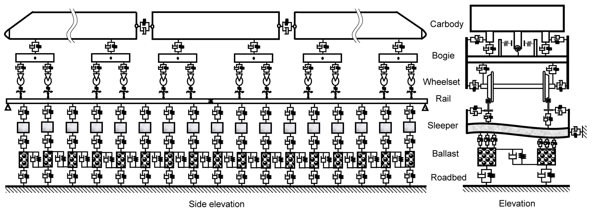
A 3D dynamic model of a high-speed train composed of multiple vehicles coupled with a ballast track is shown in Fig. 2. The coupled train/track dynamic model consists of four subsystems: the vehicle, the inter-vehicle connection, the track, and the wheel/rail contact. Each vehicle considered is equipped with a pair of two-axle bogies with double suspension systems. The wheelset and the bogie are connected by the primary suspension, while the car body is supported on the bogie through the secondary suspension. Each component of the vehicle has six degrees of freedom: the longitudinal displacement X, the lateral displacement Y, the vertical displacement Z, the rolling angle ϕ, the pitching angle β, and the yawing angle ψ. 3D spring-damper elements are used to represent the primary and the secondary suspensions, and the nonlinear dynamic characteristics of the suspension systems are considered, including the nonlinear yaw dampers, the nonlinear lateral dampers, and the nonlinear stoppers installed on the secondary suspension as well as the nonlinear vertical dampers installed on the primary suspension (Xiao et al., 2012). A detailed inter-vehicle connection model is established. The nonlinear coupler-draft gear system and nonlinear inter-vehicle dampers are replaced with unidirectional nonlinear spring-damper elements. The tight-lock vestibule diaphragm is simplified as the 3D spring element, which restrains the adjacent vehicles in the longitudinal, lateral, vertical, rolling, pitching, and yawing directions. The inter-vehicle forces can be calculated based on the deformation of the connectors and the relative angle between the connectors and the car bodies (Ling, 2012).
Fig.2 High-speed train/track coupling model
Since the vehicle system contains many differential equations and the detailed derivation of the equations is tedious (which is ignored here), the equations of motion are expressed as
,
where Mv, Cv, and Kv are the mass, damping, and stiffness matrices of the vehicle subsystem, respectively; , , and Xv are the acceleration, velocity, and displacement vectors of the vehicle subsystem, respectively; Fwr is the vector of the nonlinear wheel-rail contact forces determined by the wheel-rail contact model; Fext is the vector of external forces including gravitational forces and forces resulting from the centripetal acceleration when the vehicle negotiating the curved track; and Fiv is the vector of the nonlinear inter-vehicle contact forces due to the couplers, inter-vehicle dampers, and the tight-lock vestibule diaphragm. The equation derivations of the vehicle system and the inter-vehicle connection model, which can be seen in (Ling, 2012), are omitted here.
2.2. Track model
The model of the track is a three-layer model consisting of rails, sleepers, and ballast bed (Fig. 2). In the track model, the rails are assumed to be Timoshenko beams supported by discrete sleepers, and the effects of the vertical and lateral motions and rolling of rails on the wheel/rail creepages are taken into account. Each sleeper is treated as an Euler beam supported by uniformly distributed stiffness and damping in its vertical direction, and a lumped mass is used to replace the sleeper in its lateral direction. The ballast bed is replaced by equivalent rigid ballast bodies in the calculation model, with only the vertical motion of each ballast body taken into account. The motion of the road bed is neglected. The equivalent springs and dampers are used as the connections between rails and sleepers, between sleepers and ballast blocks, and between ballast blocks and roadbed.
The deformation of rails is described by the Timoshenko beam theory, including the bending and torsion. Using the modal synthesis method and normalized shape functions of the Timoshenko beam, the fourth-order partial differential equations of rails are converted into second-order ordinary equations as follows:
for the lateral bending motion:
for the vertical bending motion,
and for the torsional motion,
.
In Eqs. (2)–(4), qyk(t), qzk(t) and qTk(t) are the generalized coordinates of the lateral, vertical, and rotational deflections of the rail, respectively; while wyk(t) and wzk(t) are the generalized coordinates of the deflection curve of the rail with respect to the z-axis and y-axis. The material properties of the rail are indicated by the density ρ, the shear modulus G, and Young’s modulus E. The geometry of the cross section of the rail is represented by the area A, the second moments of area Iy and Iz around the y-axis and z-axis, respectively, and the polar moment of inertia I0. The shear coefficients κy=0.4057 and κz=0.5329 for the lateral and vertical bendings, respectively, and the shear coefficient K=2.473346×10⁻⁶ are obtained through a finite element analysis of the rail profile of China CN 60 using the software package ANSYS. The calculation length of the beam is denoted by ltim. Ryi and Rzi are, respectively, the lateral and vertical forces between the rail and the sleeper i. The wheel/rail forces at the wheel j in the lateral and vertical directions are represented by Fwryj and Fwrzj. Msi and MGj denote the equivalent moments acting on the rail. Yk(x), Zk(x), and Φk(x) are the kth shape function, and NMY, NMZ, and NMT are the total number of shape functions. xsi and xwj denote the longitudinal positions of the sleeper i and the wheel j, and Nw and Ns are the numbers of the wheelsets and the sleepers within the analyzed rail, respectively. The subscript i indicates the sleeper i, and j is for the wheel j, respectively.
The sleeper in the present model is treated as an Euler-Bernoulli beam with free-free ends in the vertical direction, while as a lumped mass for its lateral motion (Fig. 2). Using the modal synthesis method and the normalized shape functions of the Euler beam, the fourth-order partial differential equations of the sleeper vertical vibration can be simplified as a second-order ordinary equation as follows:
,
where qsk(t) is the generalized coordinates of the sleeper vertical deflection, Es is Young’s modulus, Is is the second moment of area of the rail cross-section about y axis, ms is the mass per unit longitudinal length, and ls is the length of the sleeper. Fbzi is the force between the sleeper and ballast body in the action point i, and RzRj is the force between the sleeper and the rail in the action point j. Zsk(y) is the kth modal function, and NMS is the total number of shape functions.
According to Newton’s Second Law, the lateral rigid motion of the sleeper can be written as
,
where FyLi and FyRi are the lateral forces between sleeper i and the left and right rails, respectively, and Fbyi is the equivalent lateral support force by the ballast body. The subscripts L and R denote, respectively, the left and right rails (wheels). The longitudinal rigid motion and rotating motions of each sleeper are neglected.
The ballast bed is replaced by equivalent rigid ballast bodies in this calculation model, and only the vertical motion of each ballast body is taken into account. The vertical motion equations of ballast bodies i are:
,
,
where FzfLi, FzrLi, FzfRi, FzrRi, and FzLRi are the vertical shear forces between the neighboring ballast bodies, and FzgLi and FzgRi are the vertical forces between the ballast bodies and the roadbed. MbL and MbR are the masses of the left and right ballast body, and g is the gravity acceleration. This ballast model can represent the in-phase and out-of-phase motions of two vertical rigid modes in the vertical-lateral plane of the track. For brevity, the detailed derivation of track system equations, which can be seen in (Xiao et al., 2011), is omitted.
2.3. Model of wheel/rail interaction
The calculation of wheel/rail contact forces includes a normal model and a tangent model. The normal model, which characterizes the relationship law of the normal load and deformation between the wheel and rail, is described by a Hertzian nonlinear contact spring with a unilateral restraint:
,
where GHertz is the wheel/rail contact constant (m/N2/3), which can be obtained using the Hertz contact theory (Jin et al., 2006). Zwrnc(t) is the normal compressing amount at wheel/rail contact point. Zwrnc(t) is strictly defined as an approach between the two distant points, the one belonging to the wheel, and the other one belonging to the rail. The wheel and the rail are assumed to be an elastic half-space. This approach is confined to the normal direction at the contact point of the wheel and the rail. Zwrnc(t)>0 indicates the wheel/rail in contact, and Zwrnc(t)≤0 indicates their separation.
The model developed by Shen et al. (1984) is used as the tangent model determining the relationship between the creepages and the total creep forces of the wheel/rail. In the tangent force calculation, firstly, wheel/rail creep forces are calculated according to the Kalker linear creep theory (Kalker, 1967), and then amended using the model of Shen-Hedrick-Elkins. The Kalker linear creep theory is only available for small creepages. With large creepages, for example, in the case of wheel/rail flange contact, the creep forces enter saturation, and then creep forces non-linearly vary with the creepages.
2.4. Evaluation criteria of railway vehicle derailment
At present two important criteria are widely used to evaluate the dynamic behavior and safety operation of high-speed trains. One is the Nadal’s criterion, denoted by Eq. (10), and the other is the wheelset loading reduction indicated by Eq. (11):
,
,
where δmax is the maximum flange angle of wheel, μ indicates the coefficient of friction between the wheel and the rail. L and V denotes, respectively, the lateral and vertical forces of the wheel and the rail, and ΔV indicates the normal loading difference of the left and right wheels of the same wheelset.
3. Numerical results and discussion
3.1. Dynamic behavior analysis of a high-speed train passing over a curved track with failed fasteners
In the analysis, the considered curved track has a radius of 7000 m and the super-elevation of 150 mm. It is assumed that five failed fasteners occur, respectively, on the low rail, the high rail, and both the rails of the circle section of the curved track. The usual track geometry irregularity is not considered. The train speed is 350 km/h. The rail fastener failure is simulated by changing the stiffness and damping coefficients of the fasteners and rail pads, and the parameter variations considered in the coupled train/track model are as follows:
where KflL(R)i and CflL(R)i stand for the lateral stiffness and damping coefficient of the fastener i, KpvL(R)i and CpvL(R)i denote the vertical stiffness and damping coefficient of the rail pad i, zrL(R)i and zspL(R)i indicate the vertical displacements of rails and sleepers in the action point i, respectively.
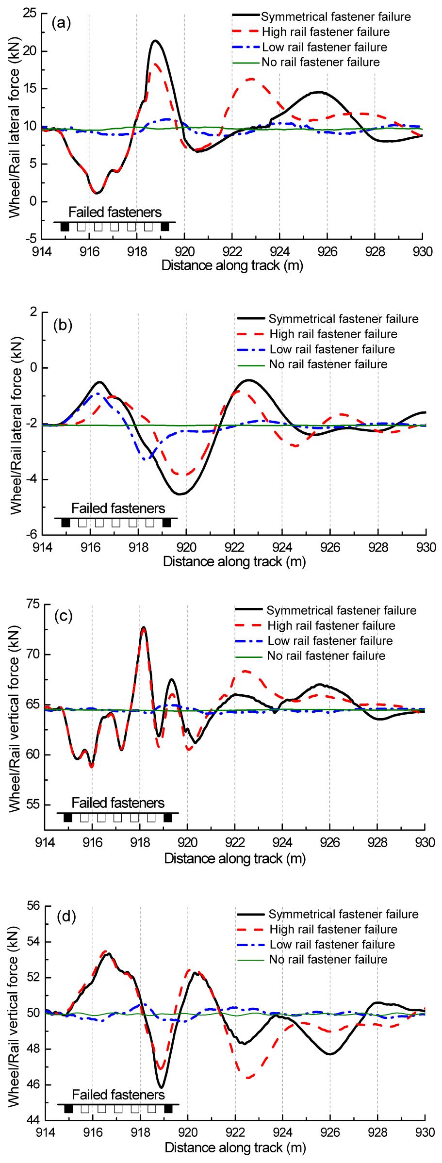
Fig. 3 illustrates the lateral and vertical forces between the rails and the first wheelset of the first vehicle when the high-speed train passes over the curved track with the different distribution of the failed fasteners at 350 km/h. “Failed fasteners” in Fig. 3 indicates the location of the five failed fasteners. It is noted that the small black boxes in the figures indicate a normal track fasteners, and the white ones correspond to the failed rail fasteners. When the high-speed train passes through the fastener failure section, the considerable impact vibrations occur between the wheels and the rails, and then they gradually decay and get into steady-state, which is similar to the track without the failure rail fasteners. Form Fig. 3, it is obvious that the forces of the wheel/rail fluctuate dramatically in the case where the fastener failure occurs on the curved track. When the first vehicle passes through the track section with five failure fasteners, the maximum lateral and vertical forces are generated on the left wheel of wheelset 1, and the minimum interaction forces are generated on the right wheel. Owing to the impact of the disabled fasteners and the external centrifugal inertial forces of the vehicle bodies when the train is negotiating the curved track, the lateral and vertical forces on the left wheel (on the high rail) are much larger than those on the right wheel of the same wheelset. In this situation, the right wheel easily jumps and loses contact with the low rail, and the high-speed train risks a jumping derailment if there is a moderate lateral impact load applied on the vehicle system, such as a cross-wind applied to the right side of the train.
Fig.3 Wheel/Rail forces in different cases of five failed fasteners (a) Lateral forces on high rail; (b) Lateral forces on low rail; (c) Vertical forces on high rail; (d) Vertical forces on low rail
Compared to the normal condition, the maximum lateral force on the high rail increases by about 10%, 83%, and 113% in the cases, respectively, where the fastener failure occurs on the low rail, high rail, and both high and low rails of the curved track. Meanwhile, the minimum lateral force on the low rail decreases by about 66%, 92%, and 125%, respectively, as indicated in Figs. 3a and 3b. With regard to the wheel/rail vertical force, the maximum vertical force on the high rail increases by about 0.95%, 12.6%, and 13%, respectively, and the minimum vertical force on the low rail decreases by about 1%, 7%, and 8.3%, respectively (Figs. 3c and 3d). These results demonstrate that failed fasteners will lead to a large variation in the lateral wheel/rail forces, which would seriously threaten the running safety of a high-speed train. In addition, the influence of the limited fastener failure on the low rail is relatively small on the wheel/rail forces, compared to the fastener failure occurring on the high rail of the curved track.
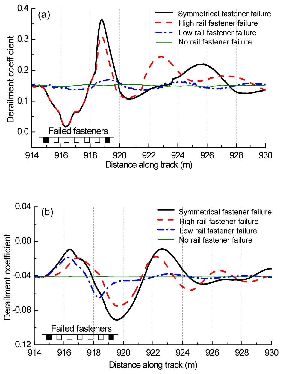
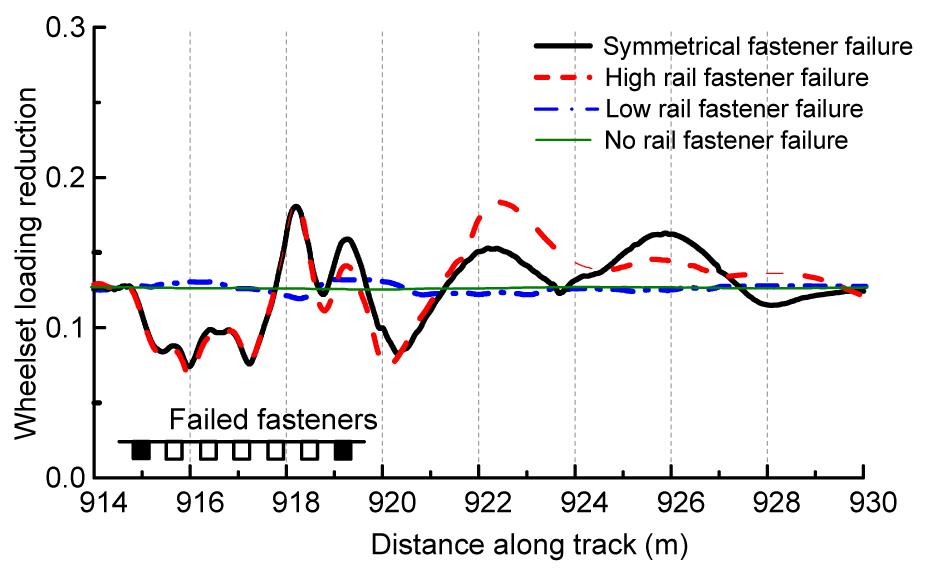
Figs. 4 and 5 indicate the derailment coefficients (L/V) and the wheelset loading reductions (ΔV/V), respectively. The variation tendencies of L/V and ΔV/V are similar to the law curves in Fig. 3 when the high-speed train negotiates the curved track with failed rail fasteners. Compared to the case without a disabled rail fastener, the maximum derailment coefficient increases by about 10%, 100%, and 136% on the high rail and decreases by about 62%, 89%, and 123% on the low rail in the respective cases where the fastener failure occurs on the low rail, high rail, and both high and low rails of the curved track, as indicated in Figs. 4a and 4b. The maximum wheelset loading reduction increases by about 6%, 47%, and 44%, respectively, as shown in Fig. 5. Although the change rates of L/V and ΔV/V are large, the derailment coefficients and the wheelset loading reduction do not exceed their limit values in the three cases of fastener failure. The limit values of L/V and ΔV/V are 0.8 (Zhang, 2011) according to the standard of the Chinese high-speed railway.
Fig.4 Derailment coefficient (L/V) in the different cases of five failed fasteners (a) High rail; (b) Low rail
Fig.5 Wheelset loading reduction ((V/V) in the different cases of five failed fasteners
Note that the maximum wheelset loading reduction in the case of five disabled fasteners occurring on the high rail is larger than that occurring on both high and low rails. Furthermore, the difference of wheelset loading reduction between the normal case and the case of five disabled fasteners occurring on the low rail is very minor. This phenomenon is much concerned with the high-speed train negotiating a curved track with the deficient super-elevation. In the present analysis case where the train speed is 350 km/h and the radius of the curved track is 7000 m, the super-elevation of 150 mm is truly undersized. In this situation, the wheel loading of the wheelsets are not symmetrical, and this asymmetrical load condition results in a train dynamic response being much related to the contact behaviour of the high rail and left wheels. When the high-speed train negotiates the curved track with disabled fasteners occurring on the high rail, the asymmetrical rail support state worsens the interaction of the wheel and the high rail.
3.2. Effect of train speed and failed fastener number
In the practical operation of high-speed trains, the operation speed always changes and the number of failed fasteners on the track is stochastic. The present model is used to calculate the combined effect of the train speed and the failed fastener number on the wheel/rail forces, L/V, and ΔV/V in order to help to maintain the high-speed track efficiently. In the calculation, it is assumed that the symmetrical failure of the fasteners on the curved track occurs. The other conditions are the same as shown in Section 3.1.
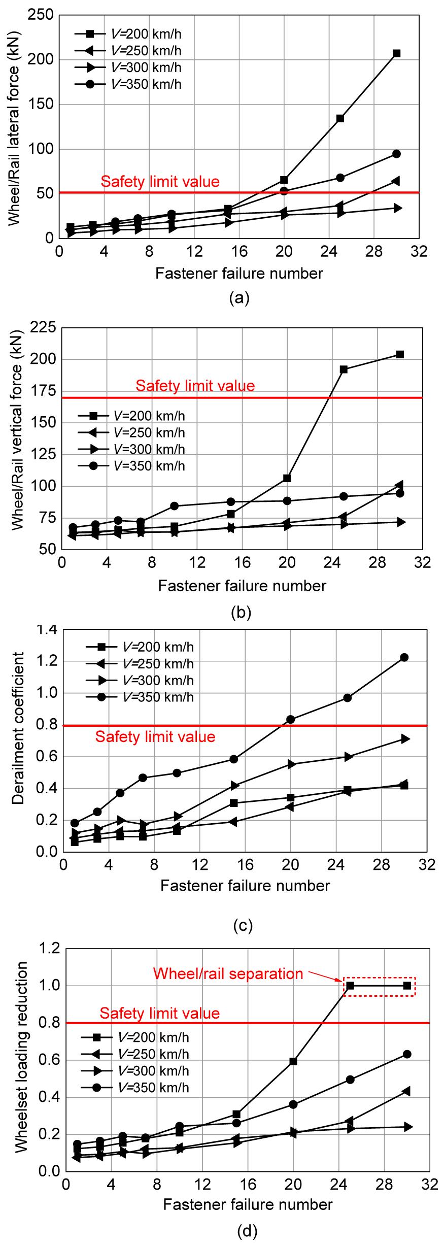
Fig. 6 indicates the effect of the failed fastener number on the maximum values of the wheel/rail forces, L/V, and ΔV/V of all the wheelsets at different speeds, where the horizontal solid lines denote their limit values. The limit value of the lateral wheel/rail forces is (10+P0/3) kN and the limit value of the vertical forces is 170 kN (Zhang, 2011), where P0 is the static load of wheelset. For each speed, the limited maximum number of the failed fasteners is determined by the minimum number of the failed fasteners in Figs. 6a–6d, namely, the smallest lateral coordinate corresponding to the intersection points of the horizontal solid lines and the corresponding curves indicating safety limit value in Fig. 6. For 200 km/h, the limited maximum number of the failed fasteners is 17, for 250 km/h it is 27, for 300 km/h it exceeds 32, and for 350 km/h, it is 18. Fig. 6a shows that the lateral force and its rate of increase with the number of fastener failures are the maximal at 200 km/h and the least at 300 km/h. The lateral force and its rate of increase at 350 km/h are the second largest. Fig. 6b shows that the situation is similar to Fig. 6a. This phenomenon is concerned with the 7000-m radius curved track with the super-elevation of 150 mm and the operation speed. When the train operation speed is 200 km/h, the super-elevation of 150 mm is oversize, and when the train speed is 350 km/h, it is undersize.
Fig.6 Safety criteria vs. train speed and fastener failure number (a) Maximum wheel/rail lateral force; (b) Maximum wheel/rail vertical force; (c) Maximum derailment coefficient; (d) Maximum wheelset loading reduction
Fig. 6c indicates that the derailment coefficient at 350 km/h is the maximal with an increase in the failed fastener number and those at 200 km/h and 250 km/h are very close. Fig. 6d illustrates that the wheelset loading reduction at 200 km/h is the maximal with an increase in the failed fastener number and those at 250 km/h and 300 km/h are very close when the number of the failed fasteners is smaller than 24. When the number of the failed fasteners exceeds 24, the wheel on the high rail comes off the rail at 200 km/h (Fig. 6d). Thus, from Fig. 6, it is known that the limited maximum numbers of the failed fasteners are different when the high-speed train passes over the curved track with the failed fasteners at different speeds. The limited maximum number of the failed fasteners changes nonlinearly with the increase of the speed.
Fig. 6 also shows that the permissible maximum numbers of the failed fasteners, determined by the limit values of the wheel/rail lateral and vertical forces, L/V, and ΔV/V, are 17, 23, 19, and 22 in the four cases of different speeds. It can be found that the disabled fasteners occurring on the high-speed curved tracks lead to the large lateral forces between the wheels and the rails. The lateral wheel/rail force and the criteria L/V reach their limit values first. These results indicate that the lateral wheel/rail force and derailment coefficient should be considered as two important criteria when disabled rail fasteners are detected in the high-speed track maintenance.
3.3. Effect of vehicle location and failed fastener number
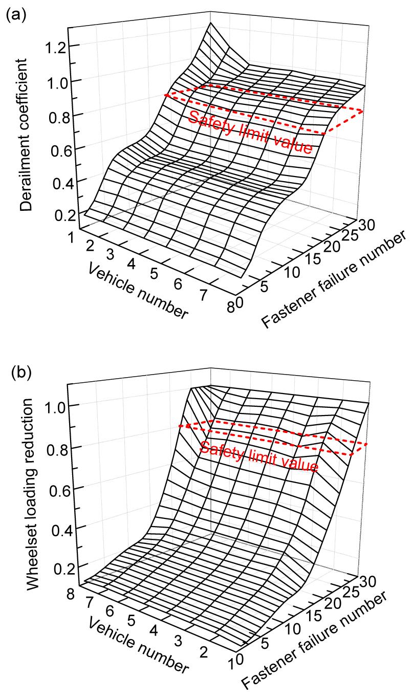
When a train passes over a curved track the dynamic behaviours of different vehicles of the same train are different. This section investigates the effect of the vehicle location and the failed fastener number on the derailment coefficient and the wheelset loading reduction of all the vehicles of the same train. Fig. 7a illustrates the maximum derailment coefficient of each vehicle when the train passes over the curved track with different numbers of failed fasteners at 350 km/h. Fig. 7b indicates the maximum wheelset loading reduction of each vehicle when the train passes over the track section with failed fasteners at 200 km/h. From Fig. 7a, the derailment coefficient of the first vehicle of the train is the maximal, and the second vehicle is the second largest. Those of other vehicles are very close. In contrast, the loading reduction of the last vehicle is the maximal, while the first vehicle is the least, as shown in Fig. 7b. From different variations of L/V and ΔV/V, the climbing derailment of the first vehicle should be of more concern when the high-speed train negotiates the curved track with disabled fasteners under the deficient super-elevation condition, and the running safety of the trailing vehicle would be in the worst situation under the surplus super-elevation condition.
Fig.7 Safety criteria vs. different vehicles and fastener failure number (a) Derailment coefficient (350 km/h); (b) Wheelset loading reduction (200 km/h)
In Fig. 7, the pane of the dash lines indicates the corresponding limit values. When the number of the failed fasteners exceeds 20, the derailment coefficient of each vehicle reaches its limit value. When the number of the failed fasteners exceeds 25, the loading reduction of each vehicle reaches its limit value. As far as the safety operation of the high-speed train is much concerned, the limited maximum number of the failed fasteners determined by the limit value of the derailment coefficient should be preferentially considered in the track maintenance due to the fastener failure. From the general trend, the derailment coefficient and the wheelset loading reduction increase quickly with the number of failed fasteners, especially when the number of failed fasteners exceeds 15.
4. Conclusions
In this paper, a coupled train-track dynamic model is introduced to investigate the effect of curved track fastener failure on the dynamic behaviour of a high-speed train passing over a curved track. The investigated dynamic behaviour includes the wheel/rail forces, the ratio of the lateral force to the vertical force of the wheel and the rail, which is called the derailment coefficient, and the wheelset loading reduction. They are very important for evaluating the safety operation of high-speed trains. Through detailed numerical investigation, we have shown the dynamic characteristics of the high-speed train and the track when the train passes over the 7000-m radius curved track with different failed fastener numbers at different speeds. When the number of the continuously failed fasteners is less than 15, the train still operates normally on the curved track of 7000-m radius at the speeds of 200 km/h to 350 km/h. The obtained results are very useful in high-speed track maintenance.
[1] Augustin, S., Gudehus, G., Huber, G., 2003. Numerical Model and Laboratory Tests on Settlement of Ballast Track. System Dynamics and Long-term Behavior of Railway Vehicles, Track and Subgrade. Springer-Verlag,Berlin :317-336.
[2] Baeza, L., Ouyang, H., 2011. A railway track dynamics model based on modal substructuring and a cyclic boundary condition. Journal of Sound and Vibration, 330(1):75-86.
[3] Biondi, B., Muscolino, G., 2003. Component-mode synthesis method for coupled continuous and FE discretized substructures. Engineering Structures, 25(4):419-433.
[4] Biondi, B., Muscolino, G., Sofi, A., 2005. A substructure approach for the dynamic analysis of train-track-bridge system. Computers and Structures, 83(28-30):2271-2281.
[5] Brabie, D., 2005. On the Influence of Rail Vehicle Parameters on the Derailment Process and Its Consequences. Licentiate Thesis, Royal Institute of Technology,Stockholm, Sweden :
[6] Cai, Y., Sun, H., Xu, C., 2008. Response of railway track system on poroelastic half-space soil medium subjected to a moving train load. International Journal of Solids and Structures, 45(18-19):5015-5034.
[7] Cheung, Y.K., Au, F.T.K., Zheng, D.Y., Cheng, Y.S., 1999. Vibration of multi-span non-uniform bridges under moving vehicles and trains by using modified beam vibration functions. Journal of Sound and Vibration, 228(3):611-628.
[8] de Salvo, V., Muscolino, G., Palmeri, A., 2010. A substructure approach tailored to the dynamic analysis of multi-span continuous beams under moving loads. Journal of Sound and Vibration, 329(15):3101-3120.
[9] Evans, J., Berg, M., 2009. Challenges in simulation of rail vehicle dynamics. Vehicle System Dynamics, 47(8):1023-1048.
[10] Frohling, R.D., 1998. Low frequency dynamic vehicle/track interaction: Modelling and simulation. Vehicle System Dynamics, 29(suppl.):30-46.
[11] Frba, L., 1999. Vibration of Solids and Structures under Moving Loads. Thomas Telford,London :
[12] Jin, X.S., Wen, Z.F., Wang, K.W., Zhou, Z.R., Liu, Q.Y., Li, C.H., 2006. Three-dimensional train-track model for study of rail corrugation. Journal of Sound and Vibration, 293(3-5):830-855.
[13] Ju, S., Lin, H., 2007. A finite element model of vehicle-bridge interaction considering braking and acceleration. Journal of Sound and Vibration, 303(1-2):46-57.
[14] Kalker, J.J., 1967. On the Rolling Contact of Two Elastic Bodies in the Presence of Dry Friction. PhD Thesis, Delft University,the Netherlands :
[15] Knothe, K., Grassie, S.L., 1993. Modeling of railway track and vehicle/track interaction at high frequencies. Vehicle System Dynamics, 22(3-4):209-262.
[16] Lei, X.Y., Mao, L.J., 2004. Dynamic response analyses of vehicle and track coupled system on track transition of conventional high speed railway. Journal of Sound and Vibration, 271(3-5):1133-1146.
[17] Ling, L., 2012. Study on the Dynamic Behaviour of High-speed Train/Track Coupling System Composed of Multiple Vehicles. MS Thesis, (in Chinese), Southwest Jiaotong University,Chengdu, China :
[18] Lou, P., 2006. Comparison of two types of deflection functions for analyzing the responses of the rail and the bridge under static or moving vehicles. Journal of Multi-body Dynamics, 220(2):105-123.
[19] Lou, P., 2007. Finite element analysis for train-track-bridge interaction system. Archive of Applied Mechanics, 77(10):707-728.
[20] National Transportation Safety Board, 1999. Railroad Accident Report, Derailment of Amtrak Train No. 4, Southwest Chief, on the Burlington Northern Santa Fe Railway near Kingman, Arizona. Report No. NTSB/RAR-98/03. National Technical Information Service,USA :
[21] Nielsen, J.C., Igeland, A., 1995. Vertical dynamic interaction between train and track-influence of wheel and track imperfections. Journal of Sound and Vibration, 187(5):825-839.
[22] Oscarsson, J., Dahlberg, T., 1998. Dynamic train/track/ballast interaction—Computer models and full-scale experiments. Vehicle System Dynamics, 29(suppl.):73-84.
[23] Popp, K., Kruse, H., Kaiser, I., 1999. Vehicle-track dynamics in the mid-frequency range. Vehicle System Dynamics, 31(5-6):423-464.
[24] Ripke, B., Knothe, K., 1995. Simulation of high frequency vehicle-track interactions. Vehicle System Dynamics, 24(suppl.):72-85.
[25] Shen, Z.Y., Hedrick, J.K., Elkins, J.A., 1984. A Comparison of Alternative Creep-force Models for Rail Vehicle Dynamic Analysis. , Proceedings of the Eighth IAVSD Symposium, Cambridge, MA, 591-605. :591-605.
[26] Sun, Y.Q., Dhanasekar, M., 2002. A dynamic model for the vertical interaction of the rail track and wagon system. International Journal of Solids and Structures, 39(5):1337-1359.
[28] Xia, H., Zhang, N., 2005. Dynamic analysis of railway bridge under high-speed trains. Computers and Structures, 83(23-24):1891-1901.
[29] Xiao, X.B., Jin, X.S., Wen, Z.F., Zhu, M.H., Zhang, W.H., 2011. Effect of tangent track buckle on vehicle derailment. Multibody System Dynamics, 25:1-41.
[30] Xiao, X.B., Ling, L., Jin, X.S., 2012. A study of the derailment mechanism of a high-speed train due to an earthquake. Vehicle System Dynamics, 50(3):449-470.
[31] Xu, Y.L., Ding, Q.S., 2006. Interaction of railway vehicles with track in cross-winds. Journal of Fluids and Structures, 22(3):295-314.
[32] Yang, Y.B., Wu, Y.S., 2001. A versatile element for analysing vehicle-bridge interaction response. Engineering Structures, 23(5):452-469.
[33] Zhai, W.M., Cai, C.B., Guo, S.Z., 1996. Coupling model of vertical and lateral vehicle/track interactions. Vehicle System Dynamics, 26(1):61-79.
[34] Zhang, S.G., 2009. Design Method of High-speed Train. (in Chinese), Chinese Railway Press,Beijing, China :
[35] Zhang, W.H., 2011. Overall Technique of EMU and Bogies. (in Chinese), Chinese Railway Press,Beijing, China :
Open peer comments: Debate/Discuss/Question/Opinion


Open peer comments: Debate/Discuss/Question/Opinion
<1>