Xiang-kai Meng, Shao-xian Bai, Xu-dong Peng. An efficient adaptive finite element method algorithm with mass conservation for analysis of liquid face seals[J]. Journal of Zhejiang University Science A, 2014, 15(3): 172-184.
@article{title="An efficient adaptive finite element method algorithm with mass conservation for analysis of liquid face seals", author="Xiang-kai Meng, Shao-xian Bai, Xu-dong Peng", journal="Journal of Zhejiang University Science A", volume="15", number="3", pages="172-184", year="2014", publisher="Zhejiang University Press & Springer", doi="10.1631/jzus.A1300328" }
%0 Journal Article %T An efficient adaptive finite element method algorithm with mass conservation for analysis of liquid face seals %A Xiang-kai Meng %A Shao-xian Bai %A Xu-dong Peng %J Journal of Zhejiang University SCIENCE A %V 15 %N 3 %P 172-184 %@ 1673-565X %D 2014 %I Zhejiang University Press & Springer %DOI 10.1631/jzus.A1300328
TY - JOUR T1 - An efficient adaptive finite element method algorithm with mass conservation for analysis of liquid face seals A1 - Xiang-kai Meng A1 - Shao-xian Bai A1 - Xu-dong Peng J0 - Journal of Zhejiang University Science A VL - 15 IS - 3 SP - 172 EP - 184 %@ 1673-565X Y1 - 2014 PB - Zhejiang University Press & Springer ER - DOI - 10.1631/jzus.A1300328
Abstract: To improve lubrication effect and seal performance, complicated geometrical hydrodynamic grooves or patterns are often processed on end faces of liquid lubricated mechanical seals. These structures can lead to difficulties in precisely estimating the seal performance. In this study, an efficient adaptive finite element method (FEM) algorithm with mass conservation was presented, in which a streamline upwind/Petrov-Galerkin (SUPG) weighted residual FEM and a fast iteration algorithm were applied to solve the lubrication equations (Reynolds equation). A mesh adaptation technique was utilized to refine the computation domain based on a residual posterior error estimator. Validation, applicability, and efficiency were verified by comparison among different algorithms and by case studies on seals’ faces with different groove structures. The study investigated the influence of the order of shape function and the mesh number on the leakage balance. Mesh refinement occurred mainly in cavitation zones when cavitation happened, otherwise it occurred in regions with a high pressure gradient. Numerical experiments verified that the proposed algorithm is a fast, effective, and accurate method to simulate lubrication problems in the engineering field apart from end face seals.
Darkslateblue:Affiliate; Royal Blue:Author; Turquoise:Article
Article Content
1. Introduction
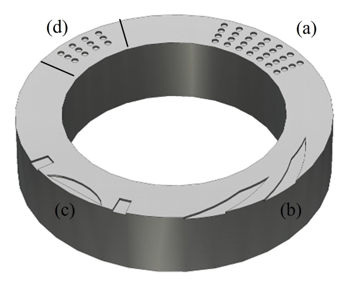
Liquid lubricated end face seals are mainly used to prevent a high pressure medium from escaping out of the machine. It includes a couple of stators and rotors respectively sitting on the house and axial of the rotary machinery. Between end faces of the couples, there exists liquid lubrication film to avoid the direct contact and severe wear. The end faces are often etched or machined with complicated geometrical hydrodynamic grooves to improve the lubrication state, decrease temperature rise and minimize leakage. These groove structures (Fig. 1) include spiral groove, circular groove, rectangle groove, and even surface textures. According to mechanical seals, the flow rate or leakage rate is a more important performance parameter than journal bearings or thrust bearings. However, it is difficult to precisely evaluate the leakage rate of mechanical seals because of the existence of complex hydrodynamic grooves and the cavitation effect resulting from Poiseuille flow and Couette flow of the lubrication film.
Fig.1 Schematics of groove pattern on seal face (a) Laser surface texture; (b) Spiral groove; (c) Laserface; (d) Partially distributed laser surface texture
According to the classical lubrication theory, the leakage rate is proportional to the film pressure gradient distribution along the normal direction of the leak boundary. Therefore, it is important to derive the exact film pressure distribution and pressure gradient from the lubrication governing equation—Reynolds equation. There are three major factors leading to difficulties in achieving a solution, i.e., (1) cavitation effect with mass conservation which implies prior uncertainties on the division of cavitation and full film zones, (2) convention dominated problems from elliptic-hyperbolic type equations which leads to unstable solutions under the high Peclet number (Zienkiewicz and Taylor, 2000), and (3) complicated hydrodynamic groove structures where the film thickness is discontinuous and high pressure differences between faces which cause more complex pressure distribution than bearings.
Nowadays, plenty of mathematical models and numerical algorithms have been proposed since Jakobsson and Floberg (1957) and Olsson (1965) presented the JFO cavitation theory. It is now the only boundary condition preserving mass conservation of fluid films. The finite difference method (FDM) (Payvar and Salant, 1992), finite volume method (FVM), finite element method (FEM), boundary element method (BEM) (Yu and Keith, 1995), and space-time conservation element and solution element method (CE/SE) (Cioc and Keith, 2003; Cioc et al., 2003) were used to solve the linear or nonlinear equation group deduced from the Reynolds equation. It is widely accepted that Elrod and Adams (1975) and Elrod (1981) initialized the successful numerical algorithm. A universal equation was proposed to describe the lubrication film by assuming that the film was compressible in non-cavitation zone and liquid/gas mixture exists in the cavitation zone, which was called the α-g model. The FDM was chosen to solve the governing equation by central and upwind difference styles (Vijayaraghavan and Keith, 1990a; 1990c). To improve the computational efficiency, Brewe (1986) introduced a multi-grid technology into the Elrod algorithm and analyzed the performance of the bearings. Pavyer and Salant (1992) presented an FVM algorithm where convection items of the equation were handled by a back difference method and an alternating direction iterative (ADI) technique was applied to speed the computational convergence. Because the above α-g model gives an unrealistic fluid film fraction (larger than 1) in the full film region for the numerical reasons from the choice of proper bulk modulus, a p-θ model is frequently used in various studies, where the JFO cavitation boundary is converted into a complementarity condition. According to the model, Ausas et al. (2007; 2009) presented an effective relaxation scheme to update the solution of satisfying complementarity conditions. Due to the capability of FEM to create a complex boundary, it was first introduced into the prediction of cavitation regions with the JFO theory by Kumar and Booker (1991; 1994) and Boedo and Booker (1995), who used Murty (1988)’s algorithm to distinguish the film rupture and reformation boundaries. Bonneau et al. (1995) and Optasanu and Bonneau (2000) used this technique to analyze dynamically loaded bearings. Bayada et al. (1990; 1998; 2006) and Durany et al. (1997; 2006) treated the cavitation as a free boundary problem and gave a series of detailed verifications. They used characteristic-Galerkin FEM and a duality iteration method to stabilize the solution. Giacopini et al. (2010) applied a linear complementary problem (LCP) method to deal with the complementarity condition and validated the algorithm on the textured bearings and squeeze film dampers in a 1D model. Hajjam and Bonneau (2004; 2007) and Fatu et al. (2005) proposed a modified p-θ FEM algorithm where a high order shape function in a non-cavitation zone and a low order shape function in a cavitation zone were used to simulate the lip seal and dynamically loaded journal bearings. Schweizer (2009) rewrote the Reynolds equation and JFO cavitation boundary to an arbitrary Lagrangian-Eulerian (ALE) problem and the FEM formulation was presented to solve some numerical examples. Due to the prior uncertainty and irregularity of film rupture and reformation boundaries, an adaptive mesh-refinement technique is frequently used to improve the computational accuracy. Vijayaraghavan and Keith (1990b) applied a grid transformation and adaption technique in the cavitated journal bearings. Case studies verified a better accuracy and lower time-consumption. Moreover, Nilsson and Hansbo (2007) applied an adaptive FEM for hydrodynamic lubrication. A posteriori error estimator and adaptive algorithms were discussed in detail with a pity of a non-mass-conserving formulation used.
In this paper, an effective mass-conserving finite element algorithm is provided for predicting the seal performance of liquid lubricated end faces etched with complex hydrodynamic grooves. A stream-upwind/Petrov-Galerkin (SUPG) weighted residual method was implemented to the compressible Reynolds equations and an FEM formulation was deduced. A fast and stable block iteration algorithm in (Shi and Salant, 1999; Shi and Paranjpe, 2002) was applied to deal with the JFO boundary condition. Film pressure and density distribution were solved simultaneously conforming to the complementarity condition. Then a classical residual posterior error was estimated, according to which the computation domain meshes were refined and the FEM formation was solved iteratively. Case studies were conducted to validate the effectiveness and efficiency of the algorithm for some conventional liquid face seals. Mass conservation characteristics and seal performance were compared by different orders of FEM shape functions and mesh adaptation techniques.
2. Mass-conserving finite element model and mesh adaptation algorithm
2.1. Governing equations
According to the lubrication film between two end faces, by applying the conventional hypothesis of lubrication theory, where the flow is assumed to be laminar and isothermal and the inertial force is neglected, the film pressure p can be solved from the compressible Reynolds equation in the orthogonal coordinates form
,
where h is the seal clearance or film thickness between two faces, and μ represents the dynamic viscosity of lubricants. U=(Ux, Uy) describes the velocity of the rotor face in the x-y coordinates. When cavitation happened, fluid film can be subdivided into two regions, full film zone and cavitation zone. The common boundaries of the two zones are called film rupture boundary and reformation boundary according to whether fluid starts to cavitate or reforms. In the full film zone, the lubricants are viewed as incompressibility, so the density ρ is constant (equal to the density of fluid film ρL) and the pressure p is larger than the cavitation pressure pc (in this study, we suppose pc=0). In the cavitation zone, a liquid/gas mixture exists, so ρ<ρL and p=pc. Then Eq. (1) can be rewritten as follows, which is an elliptic equation in the full film zone and a hyperbolic equation in the cavitation zone:
with a boundary condition on film rupture and reformation boundaries in the form of
where Un is the velocity along the normal direction n.
Boundary condition Eq. (3) preserves the mass conservation across the film rupture and reformation boundaries. If the film reformation boundary employs the same formula as the film rupture boundary, then the boundary is called a “Reynolds cavitation boundary”. For computational convenience, a new variable θ=ρ/ρL, named as the film fraction, is introduced, then Eq. (2) can be written in the following form in both the full film zone and cavitation zone
,
with complementary condition (CC) in the form
Eq. (4) with Eq. (5) is called the p-θ cavitation model, which is an elliptic-hyperbolic equation similar to the transonic potential flow (Vijayaraghavan et al., 1991). This equation is also a convection-diffusion-reaction equation. The p-θ model can be converted to an LCP and solved by Murty (1988)’s algorithm or some suitable pivoting algorithm like in (Giacopini et al., 2010).
Once the film pressure p is solved, the seal performance parameter such as the open force Fo and leakage rate Q can be easily calculated by
,
where Ω is the computational domain, that is the fluid film region, and l is the leakage boundary of the end faces. The subscriptions i and o represent the inner boundary and outer boundary of the seal faces.
2.2. Finite element variational formulation
To compute Eq. (4) with Eq. (5) by the FEM, triangular mesh is used to discrete the whole domain. The groove boundary conforms to the mesh edge, by which the different film thickness can be strictly endowed to the groove zones and non-groove zones. A Galerkin method is chosen to handle the elliptic part of Eq. (4) and the SUPG stabilized method is performed to manage the hyperbolic part by adding a numerical diffusion term (artificial viscosity) along the streamline direction (Evans, 1997; Zienkiewicz and Taylor, 2000). So the following integral weak form of Eq. (4) can be obtained by the way of integration by parts (Hajjam and Bonneau, 2004; 2007), in addition of Eq. (5) on the transition boundaries between the full film and cavitation zone
,
where w is a differentiable function defined in domain Ω, and τSUPG is the stabilization parameter which has the following form (Evans, 1997; Zienkiewicz and Taylor, 2000), , where hT is the characteristic length of each element in the direction of velocity U(Ux, Uy). That means τSUPG varies on each element.
Let w=N, p=piNi, and θ=θiNi, where N is linear or quadratic depending on the order of the shape function. The weak variational form of Eq. (7) is written as
,
where K is the stiffness matrix which can be determined by
To solve Eq. (8) with Eq. (5), it is convenient to introduce another universal variable Φ here. The form is
,
where F is the zone indicator, which is 1 in the full film zone and 0 in the cavitation zone. That is to say, Φ is equal to pressure p in the full film zone and to film fraction θ in the cavitation zone. Substituting Eq. (10) into Eq. (8), we can obtain:
,
where
,
where I is an identity matrix, and C is a matrix where all entities are zeros except the diagonal entities filled with zone indicator Fi.
An iteration procedure is performed to obtain the pressure and density distribution. Before iteration, matrixes Kp and Kθ are computed with the Gauss integration method from Eq. (9) by assembling all the element stiffness matrixes. Then the lubrication region is initially assumed to be in full film zone, that means F=1. Matrix A is calculated according to Eq. (12). Eq. (11) is solved by the generalized minimal residual method (GMRES) iteration technique and the derived variable Φ is checked whether Eq. (5) is satisfied. If Fj=1 and Φj<0, then let Fj=0; if Fj=0 and Φj>0, then let Fj=1. If Φ conforms to F, the convergent solution is gained; if not, the iteration procedure should be continued. The following case studies shows that 6–12 iterations should be conducted before convergent solutions are obtained. Note that different from Hajjam (2007)’s algorithm, the global stiffness matrix K of the present algorithm is computed only once during computation, so the algorithm is very fast and effective.
2.3. Adaptive mesh-refinement technique
Because the cavitation zone and non-cavitation zone are not distinguished until a stable solution is computed, the initial little uniform FEM meshes results in large computational errors. A remedy is the adaptive mesh-refinement technique, where the meshes are refined according to the residual posteriori error of the unknown variable Φ. The following notation similar to that in (Hajjam and Bonneau, 2004; 2007) is defined to avoid the jump of Φ across the film rupture and reformation boundaries:
Then the local residual a posteriori error η can be evaluated for every element by
,
where , where T and L respectively are the set of elements and edges, δT is the longest radius of T, δl is the length of element edge l, and [∂D/∂n] is the jump of function ∂D/∂n across the edge. According to Eq. (14), both the posteriori error of pressure in the full film zone and film fraction in the cavitation zone can be simultaneously solved. Meanwhile, the film rupture and reformation boundary position error can be estimated although unknown variable Φis discontinuous.
Once η is computed, we can use it to adapt and update the meshes. The new mesh size δk+1 is given by
,
where δ is used to control the triangular meshes sizes. is the mean of η in all element meshes. c1 and c2 are used to control the size of refinement or coarseness region. Here, c1=3 and c2=1/3 are chosen to avoid a generation of too thin or too dense meshes. From Eq. (15) we can deduce that the larger the local residual a posteriori error η is,i.e., the smaller the mesh size δ is, i.e., the meshes where the local error is large are refined.
3. Validations and case studies
3.1. Validations
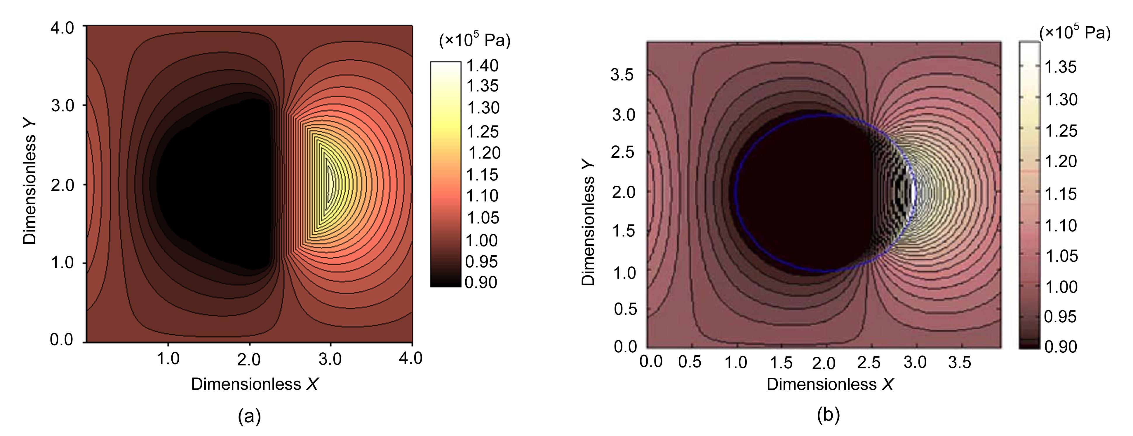
To validate the present algorithm, a comparison was conducted according to a classic journal bearing in (Elrod, 1981) and a seal face with one dimple in (Qiu and Khonsari, 2009), which are shown in Fig. 2 and Fig. 3, respectively. We can see that the present algorithm gives similar pressure distributions for the journal bearing and face seal, indicating that the present algorithm is valid.
Fig.2 Numerical results validation
Fig.3 Pressure distribution comparison with one dimple by the present algorithm (a) and Qiu and Khonsari (2009) (b)
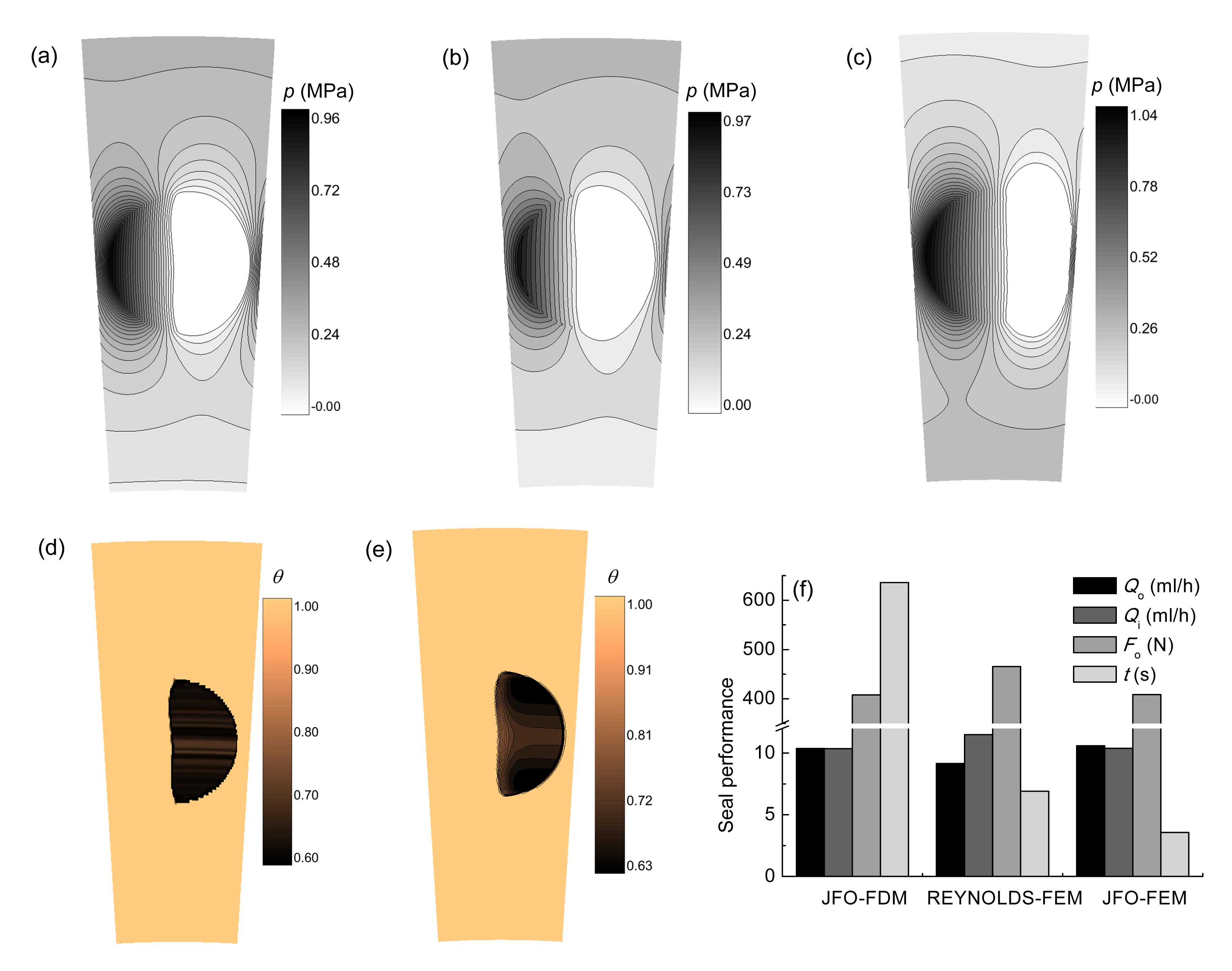
To further verify the efficiency of the algorithm, a comparison was made among different models and algorithms for a seal face etched with only one dimple (its radius is 1.5 mm). These algorithms are the present algorithm (JFO-FEM), finite difference method with JFO cavitation theory (JFO-FDM) from (Ausas et al., 2007; 2009) and FEM with Reynolds cavitation boundary condition (REYNOLDS-FEM). According to REYNOLDS-FEM, Uzawa’s algorithm (Ito and Kunisch, 2003) was applied to assure pressure satisfying the Reynolds boundary condition. Table 1 lists the value of the face geometrical parameters and operating parameters. Fig. 4 shows the pressure and film fraction distribution obtained from the above algorithms, respectively. We can see that JFO-FEM gives a similar pressure and density distribution to those from JFO-FDM. The cavitation zone (Figs. 4d and 4e) and maximum film pressure (Figs. 4a and 4b) show an excellent agreement between the two algorithms. Fig. 4c shows the pressure distribution from REYNOLDS-FEM. The maximum film pressure is larger than that in Figs. 4a and 4b from the JFO models. Furthermore, a larger cavitation zone in Fig. 4c is also found. All these results illustrate that the Reynolds cavitation boundary condition cannot provide accurate seal performance predictions.
Table 1
Seal face geometrical parameters and operating condition
Parameter
Value
Inner radius of end face, ri (mm)
24
Outer radius of end face, ro (mm)
34
Inner pressure, pi (MPa)
0.1
Outer pressure, po (MPa)
0.3
Seal faces gap, hi (μm)
2
Groove or dimple depth, hg (μm)
1.5
Viscosity of lubricants, μ (Pa·s)
1×10⁻³
Rotation speed, ω (r/min)
1500
Fig.4 Numerical results comparisons Pressure distribution of JFO-FEM (a), JFO-FDM (b), and REYNOLDS-FEM (c), film fraction from JFO-FEM (d) and JFO-FDM (e), and seal performance parameters comparison (f)
Fig. 4f gives a comparison among the above three algorithms on a cost time for computation t and the seal performance parameter, including open force Fo and flow rates, Qi and Qo. Flow rate and open force show an excellent agreement between JFO-FEM and JFO-FDM. Due to JFO model’s mass conservation, flow rate (leakage rate) Qi is approximately equal to Qo. This demonstrates the accuracy of the present model and algorithm. Although more meshes were used for the current algorithm (30 044 triangular meshes) than JFO-FDM (251×91 structured meshes), it performed in a very high efficiency which is almost 180 times higher than the later. The REYNOLDS-FEM algorithm also had a very high computation efficiency (the computation time is 6.92 s according to 30 044 triangular meshes) as JFO-FEM does, and it overestimates the open force Fo by 13.8% and yields an unequal leakage rate between Qi and Qo with a bias of 11.6%. All numerical results in Fig. 4 show that the current algorithm has a high efficiency and precision.
To examine the applicability of the current algorithm, in the following sections, some case studies were conducted on the seal performance prediction of the conventional mechanical seals such as laser textured surface (LST), spiral groove surface (SGS), laserface surface (LFS), etc. These end face structures are shown in Fig. 1. The seal face geometrical parameters and operating conditions listed in Table 1 are used to evaluate the film pressure distribution and seal performance.
3.2. Case study 1: LST mechanical seal
Etsion and Michael (1994), Etsion and Burstein (1996), and Etsion et al. (1999) invented LST mechanical seals (LST-MS), of which the surface is etched with regularly distributed micro-dimples. The dimples act as numerous micro-bearings between seal faces by which the seal performance and resistance to wear are greatly improved. In (Etsion and Michael, 1994)’s mathematical model, the Reynolds cavitation boundary condition is always applied, which overestimates the open force and is a non-mass -conservative as mentioned above. Here, our JFO-FEM algorithm was used to recalculate the seal performance and pressure distribution.
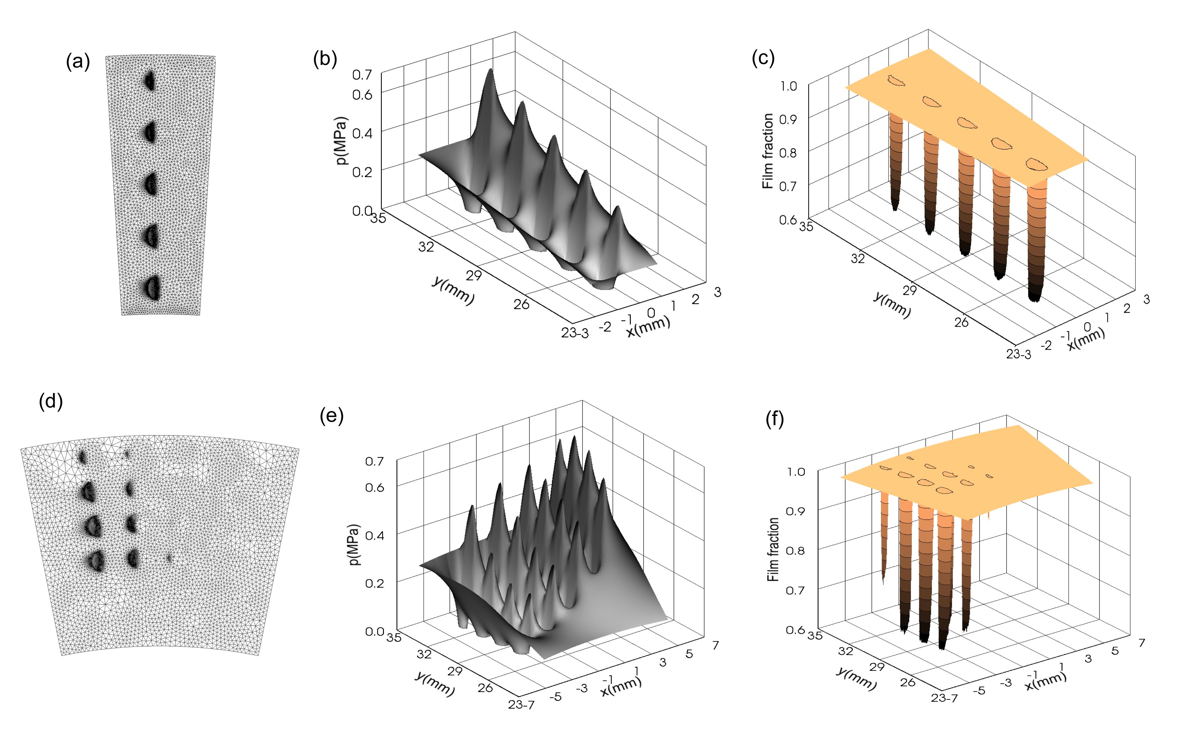
Fig. 5 shows the results from solving for LST-MS. Fig. 5a is the final FEM meshes after a few adaptations. We can see that the mesh refinement zones are clearly recognized in the cavitation region, which means larger local errors occur here. From Eq. (2) we know that governing equation describing the non-cavitation region is elliptic and that describing the cavitation region is hyperbolic. Meanwhile, the same order shape function of FEM elements are used in the lubrication region, so computation accuracy in the cavitation region is lower than in the full film region. Fig. 5b illustrates the film pressure distribution. It can be seen that the local maximum pressure exists at the convergent step of every dimple, while the cavitation occurs at the divergent step. Moreover, the global maximum pressure appears at the high pressure side. Fig. 5c shows the density distribution of LST-MS, where θ=1 means the zone belongs to the full film zone and θ<1 determines the cavitation zones. The cavitation zone area of every dimple increases along the radial direction from the outer side to inner side. This indicates that low pressure can easily lead to occurrence of a cavitation. To further improve the dynamic effect of micro-dimples, a partially distributed LST-MS (PLST-MS) is introduced by Etsion and Michael (1994). Figs. 5d–5f show the computation results of PLST-MS with 4×4 micro-dimples. Mesh refinement zones are also located in the cavitation region just as in LST-MS. The apparent ‘accumulation effect’ can be seen in Fig. 5e. The local maximum pressure of every dimple increases from the inner side to outer side and along the film flow circumference direction. Local minimum density (Fig. 5f) shows the same rules as the maximum pressure does. Comparisons were made on the seal performance with different mesh numbers, orders of FEM shape function N, and mesh adaptation. Simulation results of LST and PLST are listed in Table 2. We can see that the mesh number, order of N and mesh adaptation have little influence on the open force Fo, while the leakage rate is greatly influenced by these factors. The higher order shape function and larger mesh number give a more accurate evaluation of the balance between Qi and Qo, defined as 2|(Qo−Qi)/(Qo−Qi)|. JFO-FEM with a mesh adaptation technique with the first order of N gives about the same accuracy of the leakage rate as JFO-FEM without an adaptation technique with the second order of N. These results demonstrate that the proposed mesh adaptation JFO-FEM algorithm has high applicability and accuracy for analyzing seal performance and optimizing micro-dimples’ distribution of LST-MS.
Fig.5 Mesh of LST-MS (a) and PLST-MS (d) with refinement, pressure distribution of LST-MS (b) and PLST-MS (e), and density distribution of LST-MS (c) and PLST-MS (f)
Table 2
Influence of mesh, order of N, and adaptive technique on seal performance of LST-MS and PLST-MS
End face
Algorithm
Mesh number
Order of N
Fo (N)
Qo (ml/h)
Qi (ml/h)
LST
JFO-FEM without adaptation
2694
1
385.910
−12.897
10.828
17.44%
2
385.195
−10.219
9.986
2.30%
5544
1
386.781
−10.729
10.437
2.76%
2
384.774
−10.578
9.817
7.46%
JFO-FEM with adaptation
15 165
1
390.453
−10.587
10.144
4.28%
PLST
JFO-FEM without adaptation
7112
1
401.779
−13.375
10.131
27.60%
2
400.987
−9.761
9.995
2.37%
8978
1
402.588
−9.990
10.148
1.57%
2
402.355
−10.156
10.090
0.65%
JFO-FEM with adaptation
10 643
1
404.770
−10.299
10.147
1.49%
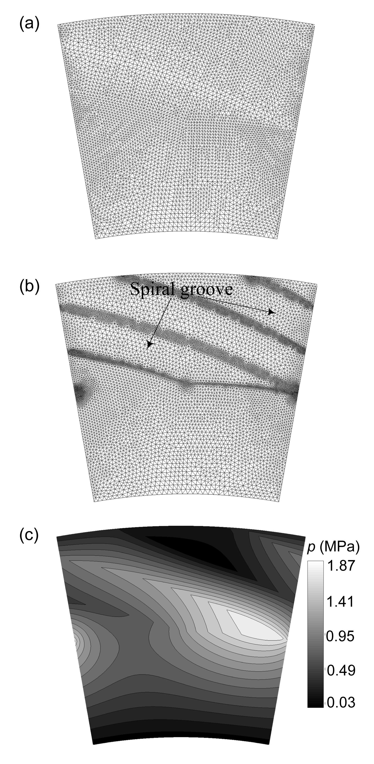
3.3. Case study 2: spiral groove end face seals (SGS)
In this section, another case study was conducted according to spiral groove end face seals (SGS) where spiral grooves were etched to improve their hydrodynamic effect. Fig. 6 illustrates the computation region meshes with and without mesh adaptation and the final pressure distribution. We can see that the mesh refinement mainly happens at the steps and sharp corners of the spiral grooves where the high pressure gradient occurs. The hydrodynamic effect of spiral grooves leads to a high pressure distribution at the sharp corner and a low one at the entrance of the grooves. Under the current geometric structure and operating conditions used, no cavitation zone is predicted. Table 3 lists the influence of the mesh number, order of shape function N, and mesh adaptation on the computation accuracy of the SGS’ seal performance. Same as in LST-MS, a large mesh number, high order of N, and mesh adaptation technique give rise to high accuracy on the balance between Qi and Qo, while having little impact on the open force Fo. Compared with LST, SGS shows a more excellent hydrodynamic and severe leakage rate. This case study demonstrates that the current JFO-FEM algorithm and mesh adaptation technique are applicable and effective in precisely estimating seal performance of end face seals with no cavitation occurrence.
Fig.6 Spiral groove end face seals (a) Initial mesh; (b) Mesh after refinement; (c) Pressure distribution
Table 3
Influence of mesh, order of N, and adaptive technique on seal performance of SGS
Algorithm
Mesh number
Order of N
Fo (N)
Qo (ml/h)
Qi (ml/h)
JFO-FEM without adaptation
6596
1
1389.95
−101.823
92.841
9.23%
2
1390.26
−97.215
93.252
4.16%
16 571
1
1389.01
−100.338
92.820
7.78%
2
1388.47
−97.422
93.078
4.46%
JFO-FEM with adaptation
16 269
1
1386.93
−96.337
92.774
3.77%
3.4. Case study 3: laserface end face seals (LFSs)
To further verify the high efficiency of the current algorithm, a more complex hydrodynamic combination grooves end face seals called laserface seals (LFSs) were investigated, including rectangular grooves and crescent-shaped grooves spaced alternately with each other (Fig. 1). The rectangular grooves, called inlet grooves, introduce the fluid into the seal face clearance. Crescent-shaped grooves, called return grooves, force the fluid to the outer periphery of the seal. The fluid film thickness is described by where a and b are parameters determining the shape of the return groove, ly denotes the position of the groove and c represents the return groove deepness.
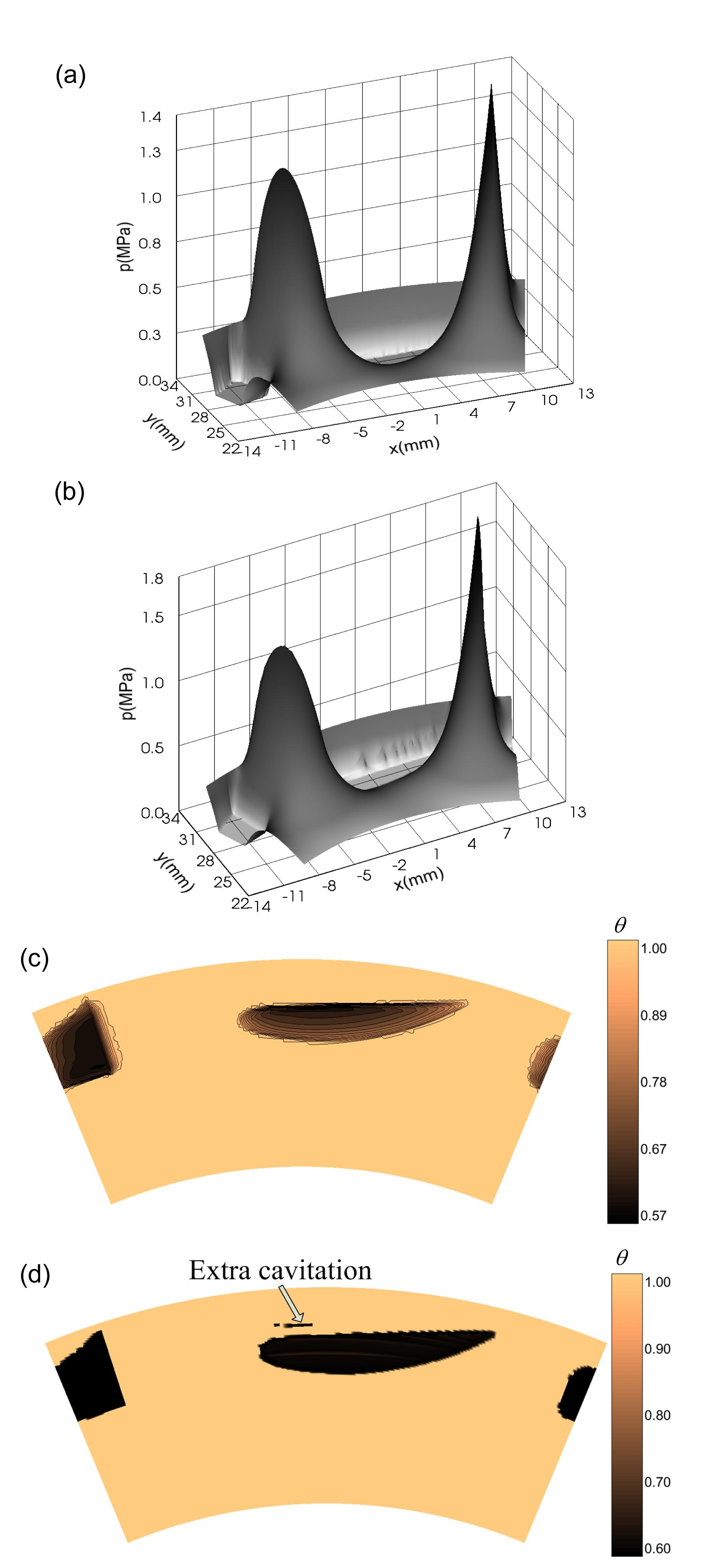
Fig. 7 shows film pressure and density distribution of the periodic face structure obtained from JFO-FEM with mesh adaptation and JFO-FDM. Due to the hydrodynamic effect of the grooves, two pressure peaks are shown respectively in the inlet groove and return groove. At the same time, two cavitation zones are shown. This type of pressure profile shows the existence of high pressure gradients on the outer side of the seal face, which reduces the accuracy of the leakage rate Qo. Thus, fine meshes or mesh adaptation techniques are recommended to be utilized here. Similar pressure and density distribution are shown in Figs. 7a and 7b except for existence of local spikes around the return groove cavitation zone in Fig. 7b and extra biased predicting cavitation zone in Fig. 7d, which are the results from JFO-FDM. These errors are primarily induced by the inconsistencies between the structured mesh of JFO-FDM and the complicated groove boundaries. To remove these mesh errors, unstructured meshes should be generated, whose edge is strictly consistent with the groove boundaries just as those used in the current JFO-FEM algorithm.
Fig.7 Laserface end face seals Pressure distribution with JFO-FEM (a) and JFO-FDM (b), and density distribution with JFO-FEM (c) and JFO-FDM (d)
Table 4 shows the influence of different algorithms, mesh numbers and order of N on the predicted seal performance. JFO-FEM with mesh adaptation techniques provides a most accurate leakage rate prediction. Numerical experiments show that JFO-FDM provides a high open force and high time consumption for computation. This case study demonstrates that the current algorithm is greatly free in dealing with end face seals with complicated groove patterns.
Table 4
Influence of mesh, order of N and adaptive technique on seal performance of LFS
Algorithm
Mesh number
Order of N
Fo (N)
Qo (ml/h)
Qi (ml/h)
JFO-FEM without adaptation
8785
1
409.322
−8.945
9.960
10.74%
2
408.265
−11.857
9.835
18.64%
16 764
1
414.471
−11.695
10.201
13.65%
2
413.451
−10.734
10.092
6.17%
JFO-FEM with adaptation
12 723
1
420.995
−11.117
10.505
5.66%
JFO-FDM
150×200
−
446.407
−13.328
11.650
13.44%
4. Conclusions
In this paper, an effective adaptive FEM algorithm with mass conservation is presented to analyze the seal performance of end face liquid seals with complicated hydrodynamic groove patterns. The classical p-θ cavitation model was used to describe the lubrication problem between end faces. The SUPG stabilization technique was brought into the FEM procedure to deal with the elliptic-hyperbolic equation. An effective numerical iterative algorithm was applied to handle the complementary relationship between pressure and density. The mesh adaptation technique was introduced into the algorithm to precisely predict the seal performance based on the residual posterior error estimation. Numerical result comparisons were conducted among the present algorithm, JFO-FDM, and REYNOLDS-FEM to analyze seal performance of end face seals with different groove patterns. Numerical experiments demonstrate that the adaptive technology gives accurate results with low order shape function. The SUPG technology stabilizes the numerical results and provides the smooth pressure and film fraction distribution. The refinement of mesh mainly occurs in the cavitation zone and large pressure gradient zones. The proposed algorithm is especially capable to simulate lubrication problems with complicated surface patterns.
[1] Ausas, R.F., Ragot, P., Leiva, J., 2007. The impact of the cavitation model in the analysis of microtextured lubricated journal bearings. ASME Journal of Tribology, 129(4):868-875.
[2] Ausas, R.F., Jai, M., Buscaglia, G.C., 2009. A mass-conserving algorithm for dynamical lubrication problems with cavitation. ASME Journal of Tribology, 131(3):031702
[3] Bayada, G., Chambat, M., Alaoui, M.E., 1990. Variational formulations and finite element algorithms for cavitation problems. ASME Journal of Tribology, 112(2):398-403.
[4] Bayada, G., Chambat, M., Vazquez, C., 1998. Characteristics method for the formulation and computation of a free boundary cavitation problem. Journal of Computational and Applied Mathematics, 98(2):191-212.
[5] Bayada, G., Martin, S., Vazquez, C., 2006. Micro-roughness effects in (elasto)hydrodynamic lubrication including a mass-flow preserving cavitation model. Tribology International, 39:1707-1718.
[6] Boedo, S., Booker, J.F., 1995. Cavitation in normal separation of square and circular plates. ASME Journal of Tribology, 117:403-409.
[7] Bonneau, D., Guines, D., Frene, J., 1995. EHD analysis, including structural inertia effects and a mass-conserving cavitation model. ASME Journal of Tribology, 117(3):540-547.
[8] Brewe, D.E., 1986. Theoretical modeling of the vapor cavitation in dynamically loaded journal bearings. ASME Journal of Lubrication Technology, 108(4):628-638.
[9] Cioc, S., Keith, T.G., 2003. Application of the CE/SE method to two-dimensional flow in fluid film bearings. International Journal of Numerical Methods for Heat & Fluid Flow, 13(2):216-243.
[10] Cioc, S., Florin, F., Keith, T.G., 2003. Application of the CE/SE method to wave journal bearings. STLE Tribology Transactions, 46(2):179-186.
[11] Durany, J., Garcia, G., Vasquez, C., 1997. An elasto-hydrodynamic coupled problem between a piezoviscous Reynolds equation and a hinged plate model. Modlisation Mathmatique et Analyse Numrique, (in French),31(4):495-516.
[12] Durany, J., Pereira, J., Varas, F., 2006. A cell-vertex finite volume method for thermohydrodynamic problems in lubrication theory. Computer Methods in Applied Mechanics and Engineering, 195(44-47):5949-5961.
[13] Elrod, H.G., 1981. A cavitation algorithm. Journal of Lubrication Technology, 103(3):350-354.
[14] Elrod, H.G., Adams, M.L., 1975. A computer program for cavitation and starvation problems. , Proceedings of 1st Leeds-Lyon Symposium on Tribology, New York, 37-42. :37-42.
[15] Etsion, I., Michael, O., 1994. Enhancing sealing and dynamic performance with partially porous mechanical face seals. Tribology Transactions, 37(4):701-710.
[16] Etsion, I., Burstein, L., 1996. A model for mechanical seals with regular micro-surface structure. Tribology Transactions, 39(3):677-683.
[17] Etsion, I., Kligerman, Y., Halperin, G., 1999. Analytical and experimental investigation of laser-textured mechanical seal faces. Tribology Transactions, 42(3):511-516.
[18] Evans, L.C., 1997. Partial Differential Equations. , American Mathematical Society, Berkeley, USA, 398-431. :398-431.
[19] Fatu, A., Hajjam, M., Bonneau, D., 2005. An EHD model to predict the interdependent behavior of two dynamically loaded hybrid journal bearings. ASME Journal of Tribology, 127(2):416-424.
[20] Giacopini, M., Fowell, M.T., Dini, D., 2010. A mass-conserving complementarity formulation to study lubricant films in the presence of cavitation. ASME Journal of Tribology, 132:041702
[21] Hajjam, M., Bonneau, D., 2004. Elastohydrodynamic analysis of lip seals with microundulations. Proceedings of the Institution of Mechanical Engineers, Part J: Journal of Engineering Tribology, 218(1):13-21.
[22] Hajjam, M., Bonneau, D., 2007. A transient finite element cavitation algorithm with application to radial lip seals. Tribology International, 40:1258-1269.
[23] Ito, K., Kunisch, K., 2003. Semi-smooth Newton methods for variational inequalities of the first kind. ESAIM: Mathematical Modelling and Numerical Analysis, 37(1):41-62.
[24] Jakobsson, B., Floberg, L., 1957. The finite journal bearings considering vaporization. Transactions of Chalmers University of Technology, 190:1-116.
[25] Kumar, A., Booker, J.F., 1991. A finite element cavitation algorithm. ASME Journal of Tribology, 113(2):276-286.
[26] Kumar, A., Booker, J.F., 1994. A mass and energy conserving finite element lubrication algorithm. ASME Journal of Tribology, 116(4):667-671.
[27] Murty, K.G., 1988. Linear Complementarity, Linear and Nonlinear Programming. Heldermann Verlag,Berlin, Germany :361-377.
[28] Nilsson, B., Hansbo, P., 2007. Adaptive finite element methods for hydrodynamic lubrication with cavitation. International Journal for Numerical Methods in Engineering, 72(13):1584-1604.
[29] Olsson, K.O., 1965. Cavitation in dynamically loaded bearing. Transactions of Chalmers University of Technology, 308:1-59.
[30] Optasanu, V., Bonneau, D., 2000. Finite element mass-conserving cavitation algorithm in pure squeeze motion. validation/application to a connecting-rod small end bearing. ASME Journal of Tribology, 122:162-169.
[31] Payvar, P., Salant, R.F., 1992. Computational method for cavitation in a wavy mechanical seal. ASME Journal of Tribology, 114(1):199-204.
[32] Qiu, Y., Khonsari, M.M., 2009. On the prediction of cavitation in dimples using a mass-conservative algorithm. ASME Journal of Tribology, 131(4):041702
[33] Schweizer, B., 2009. Numerical approach for solving Reynolds equation with JFO boundary conditions incorporating ALE techniques. ASME Journal of Tribology, 131(1):011702
[34] Shi, F., Salant, R.F., 1999. A mixed soft elastohydrodynamic lubrication model with interasperity cavitation and surface shear deformation. ASME Journal of Tribology, 122(1):308-316.
[35] Shi, F., Paranjpe, R., 2002. An implicit finite element cavitation algorithm. CMES, 3:507-515.
[36] Vijayaraghavan, D., Keith, T.G., 1990. An efficient, robust, and time accurate numerical scheme applied to a cavitation algorithm. ASME Journal of Tribology, 112(1):44-51.
[37] Vijayaraghavan, D., Keith, T.G., 1990. Grid transformation and adaption techniques applied in the analysis of cavitated journal bearings. ASME Journal of Tribology, 112(1):52-59.
[38] Vijayaraghavan, D., Keith, T.G., 1990. Analysis of a finite grooved misaligned journal bearing considering cavitation and starvation effects. ASME Journal of Tribology, 112(1):60-67.
[39] Vijayaraghavan, D., Keith, T.G., Brewe, D.E., 1991. Extension of transonic flow computational concepts in the analysis of cavitated bearings. ASME Journal of Tribology, 113(3):539-546.
[40] Yu, Q., Keith, T.G., 1995. Prediction of cavitation in journal bearings using a boundary element method. ASME Journal of Tribology, 117:411-421.
[41] Zienkiewicz, O.C., Taylor, R.L., 2000. The Finite Element Method. Nutterworth-Heinemann,Oxford, England :15-23.
Open peer comments: Debate/Discuss/Question/Opinion


Open peer comments: Debate/Discuss/Question/Opinion
<1>