Affiliation(s):
. State Key Laboratory of Fluid Power Transmission and Control, Department of Mechanical Engineering, Zhejiang University, Hangzhou 310027, China
Wen-feng Gan, Jian-zhong Fu, Hong-yao Shen, Zhi-wei Lin. A morphing machining strategy for artificial bone[J]. Journal of Zhejiang University Science A, 2014, 15(3): 157-171.
@article{title="A morphing machining strategy for artificial bone", author="Wen-feng Gan, Jian-zhong Fu, Hong-yao Shen, Zhi-wei Lin", journal="Journal of Zhejiang University Science A", volume="15", number="3", pages="157-171", year="2014", publisher="Zhejiang University Press & Springer", doi="10.1631/jzus.A1300274" }
%0 Journal Article %T A morphing machining strategy for artificial bone %A Wen-feng Gan %A Jian-zhong Fu %A Hong-yao Shen %A Zhi-wei Lin %J Journal of Zhejiang University SCIENCE A %V 15 %N 3 %P 157-171 %@ 1673-565X %D 2014 %I Zhejiang University Press & Springer %DOI 10.1631/jzus.A1300274
TY - JOUR T1 - A morphing machining strategy for artificial bone A1 - Wen-feng Gan A1 - Jian-zhong Fu A1 - Hong-yao Shen A1 - Zhi-wei Lin J0 - Journal of Zhejiang University Science A VL - 15 IS - 3 SP - 157 EP - 171 %@ 1673-565X Y1 - 2014 PB - Zhejiang University Press & Springer ER - DOI - 10.1631/jzus.A1300274
Abstract: In this work, a novel morphing machining strategy (MMS) is proposed. In the method, the workpiece is progressively carved out from the stock. Pitfalls in conventional iso-height strategy, such as sharp edges and unevenly distributed left-over materials, are overcome. Moreover, to calculate different levels in the MMS, an energy-based morphing algorithm is proposed. Finally, the proposed strategy is employed in the machining of artificial bone represented by a t-spline surface. The excellent properties of T-spline, such as expressing complex shapes with a single surface, have been well adopted to artificial bone fabrication. Computer simulation and the actual machining of the middle finger bone show the feasibility of the proposed strategy.
Darkslateblue:Affiliate; Royal Blue:Author; Turquoise:Article
Article Content
1. Introduction
Each year, millions of patients all over the world suffer from bone defects or orthopedic injury (Porter et al., 2009). Ordinary bone repairing methods include autologous transplant, allograft transplant, and artificial bone implant. Of these, the artificial method is most widely used in clinical practice while the other two methods are subject to limited transplant resources or to biological rejection. Artificial bones/braces/joints are biological functional parts made out of polymer, ceramic, or metal alloy. They are designed to mimic the afflicted part or optimized shape, and to serve as a substitute for the damaged bone. Compared to common mechanical parts, complex surfaces and strange shapes are often required in artificial bones. Traditional three-axis machining is incapable of manufacturing such items. Five-axis machine tools and high speed machining are usually employed to ensure precision and quality. New processing technologies such as 3D printing (Porter et al., 2009) and laser sintering (Su et al., 2012) have also been reported in artificial bone manufacture.
Due to the physical differences between patients, the shape of the artificial bone should be customized and personalized. Bone models are regenerated from a computed tomography (CT) scanning result or a data point cloud. The reconstruction and representation of the bone model is an issue of concern. Discrete models (Kim, 2010), such as polyhedron and triangular mesh, have been widely embraced by academics and industry because their structure and geometric computation are simple. However, when representing complex shapes, a finer mesh will be employed and the number of facets will greatly increase. A large storage memory is required and the geometric computation time becomes unaffordable. Furthermore, geometric properties such as normal vectors, curvatures, and geodesic curves in discrete models are calculated approximately. Analytical surfaces, such as tensor-product non-uniform rational B-splines (NURBS) (Xu et al., 2013), have become the de facto industry standard in computer-aided design (CAD) and computer-aided manufacturing (CAM). Nevertheless, due to the nature of the tensor-product, multiple trimmed NURBS patches (Sarkar and Dey, 2013; Zhu et al., 2013) should be used to represent the complex shapes of artificial bones. The trimming and joining process will leave cracks between adjacent patches, as shown in Fig. 1. These unwanted entities not only lower surface precision but hinder tool path generation as well. In order to overcome the disadvantages of NURBS, T-spline (Sederberg et al., 2003; 2004) comes into being. The main improvement of T-spline from tensor-product NURBS is in its pre-images. The shape of a T-spline pre-image is not necessarily a rectangle. Also, the numbers of knots on each row are not necessarily the same. The casual topological structure of T-spline makes it convenient for expressing complex shapes. Nowadays, T-spline has been widely used in design (Yang and Zheng, 2012), virtual reality (Chen et al., 2011), and product analysis (Bazilevs et al., 2010). The Autodesk® T-splines® Plug-in for Rhino® is now the only 3D modeling tool using T-splines in the world. Inspired by the idea of the uneven control mesh, the polynomial splines over hierarchical T-meshes (PHT) (Deng et al., 2008) have also been proposed. It has shown great potential in the field of computer-aided engineering (CAE) (Nguyen-Thanh et al., 2011a; 2011b). In spite of the successful implementation of T-spline in the above-mentioned fields, its application in medical care has not been exploited. With the help of T-spline, the complex shape of an artificial bone can be easily reconstructed by a single surface. Tedious molding turnover can be avoided, thus the rebuild and manufacture cycle will be faster and the suffering of the patient can be greatly relieved.
Fig.1 Middle finger bone in three representation (a) Modeled by four trimmed NURBS patches. Small crack appears on the boundary between adjacent patches; (b) Triangular mesh with 1032 vertices and 2060 facets; (c) A rendered view of the bone model in single T-spline surface
Conventionally, an iso-height strategy is used as the roughing process, as shown in Fig. 2. The cutter sweeps over the stock in layers of the same height or, in the case of a revolving part, the same diameter. The resulting materials exhibit stair-case shapes which become obstacles in the subsequent finishing process (Lauwers and Lefebvre, 2006). For one thing, uncut materials are left over unevenly across the workpiece. A widely varying cutting depth will be encountered during finishing. In addition, the sharp edges of layers undermine tool durability. To reduce the influence of stair-case residual material, a finer cutting depth interval should be chosen. After that, a semi-finish process must be conducted before finishing. These compensation methods in turn cost extra machining time and tool wear. Moreover, artificial bones are usually long and slender parts. The sudden change of cutting depth will exert a great impact on weak portions of the workpiece. This will cause deviation, machining error, or even fracture, especially when aluminum and titanium alloys are used as artificial bone materials.
Fig.2 Comparison between traditional iso-height strategy and morphing machining strategy (MMS) (a) Iso-height machining induces uneven left-over with sharp edges; (b) In MMS, cutting depths on each level are smoothly and evenly distributed
In this work, we will propose a novel morphing machining strategy (MMS). Instead of roughing on iso-height layers, the final design surface is progressively carved out from the stock. No semi-finish process is required. On every level, the cutting depth is constrained within predefined parameters and evenly distributed, ensuring that no defect occurs during the whole machining process. Moreover, in order to calculate the different levels in MMS, an energy-based morphing algorithm is proposed. By minimizing the inner and external energy under constraints, the original surface gradually morphs to the target surface. Finally, the proposed strategy is employed in the machining of artificial bone represented by a T-spline surface. The excellent properties of T-spline, such as expressing complex shapes with a single surface, are adopted to artificial bone fabrication. This work is the first attempt to apply T-spline in the area of medical care.
The main contributions of this study are:
A novel morphing machining strategy is proposed.
An energy-based surface morphing method for T-spline surface is developed and used for level generation in MMS.
An application of MMS fabrication to an artificial finger bone is proposed.
2. Related works
A detailed review of the fabrication of artificial bones and joints can be found in (Giannatsis and Dedoussis, 2009; Porter et al., 2009). Compared to other methods such as mold casting, direct machining produces a better result because no shrinkage or thermal induced dimensional deviation takes place (Da Costa and Lajarin, 2012). He et al. (2006) developed a fabrication method for a customized half-knee joint substitute. The bone model and the knee joint model were fitted from discrete sampling points using commercial software. Then powder sintering and metal casting are employed to manufacture the artificial bone and joint, respectively. Su et al. (2012; 2013) introduced laser sintering to produce artificial femur using titanium alloy. The porous structure could lower weight and increase biocompatibility. However, due to the thermal effect, it resulted in a lower geometric precision compared with direct machining. The inner structure of artificial bone was discussed by Lian et al. (2006). Three different types of architecture were described and mechanical properties and porosity were tested. Wu et al. (2009) introduced a systematic procedure for repairing defective skull bone. With the help of CT scanning and commercial reverse engineering software, a stereo lithography (STL) free-form model was reconstructed. In a similar area, an integrated manufacturing system for dental crowns and bridges is reported in (Gaspar and Weichert, 2013). The tooth model was reconstructed and represented in an implicit level set model. Iso-geodesic and iso-planar methods were employed for finishing tool path generation.
In the field of tool path planning for roughing from stock, early researchers (Hu et al., 1998; Chen and Hu, 1999) employed a height map to represent the workpiece and divided it into iso-height layers. The practice was taken up in industry and research. Chuang and Wang (2000) improved the method by slicing layers of different thickness adaptively. Once the slicing is done, researchers focus on the tool path offsetting and linking within a single layer (Kim and Yang, 2008; Lin et al., 2013). The method has also been used in dental restoration machining (Dai et al., 2013). Nevertheless, as discussed in Section 1, the iso-height strategy is after all a 2.5D method. Not only will it leave unsatisfactory features, such as sharp edges and uncut materials, but the method itself will fail when machining the complex geometry of artificial bone. Lauwers and Lefebvre (2006) discussed the issue in detail and called for a solution using morphing. Inspired by the concept of incremental punching in sheet metal forming (Luo et al., 2010), where the workpiece is increasingly deformed from stock to the final shape, in this study we propose a morphing machining algorithm.
There are fruitful research on surface deformation and morphing (Moore and Molloy, 2007; Botsch, 2008). Morphing techniques are often very complex. Given an original shape and a target shape, there are infinite transformations that create a metamorphosis sequence. Free-form deformation (FFD) (Sederberg and Parry, 1986; Song and Yang, 2005) is a traditional method. The object is embedded inside a tri-variant space, and is deformed with respect to affine deformation of the coordinates. The disadvantage is that it is difficult for the deformed object to precisely fit the target shape. Level set (Yang and Juttler, 2007) is another powerful tool for 3D metamorphosis; however, its computational cost is too expensive. As a preprocess, the surface must first be discretized into data points. After the deformation, the surface is fitted again from the sampling points on the zero-level. The disadvantage of this method is that the topological structure of the original surface is discarded during the discretization process. Usually in CAM applications, the topology should be carefully preserved because it may imply features and functions of the part. The energy-based method (Hu et al., 2001; Botsch, 2008) has the reputation of being simple, robust, and easy to implement. Energy-minimized deformation has been successfully used with mesh surface, but the mass number of nodes on the mesh becomes a calculation issue. In this work, we will apply the method on T-spline surface with a vertices-based deformation calculation. Because T-spline surface can represent complex shape with less control vertices, computation complexity will be greatly reduced.
The rest of this paper is arranged as follows: in Section 3, the concept and definition of the T-spline surface will be reviewed. After that, the bone surface will be reconstructed from data points. With the finger bone model, we propose our morphing machining in Section 4. An energy-based morphing process will create a series of internal surfaces. Within each of them, a zig-zag tool path is employed to gradually carve out the part surface from stock. Computer simulation and actual machining will be given in Section 5. Section 6 concludes our work and points out the possible improvements for future research.
3. Bone surface reconstruction using T-spline
3.1. T-spline surface
In this section, we briefly review the T-spline surface and three forms of definition are given. Each will be useful in later sections for fitting, skinning, and deformation.
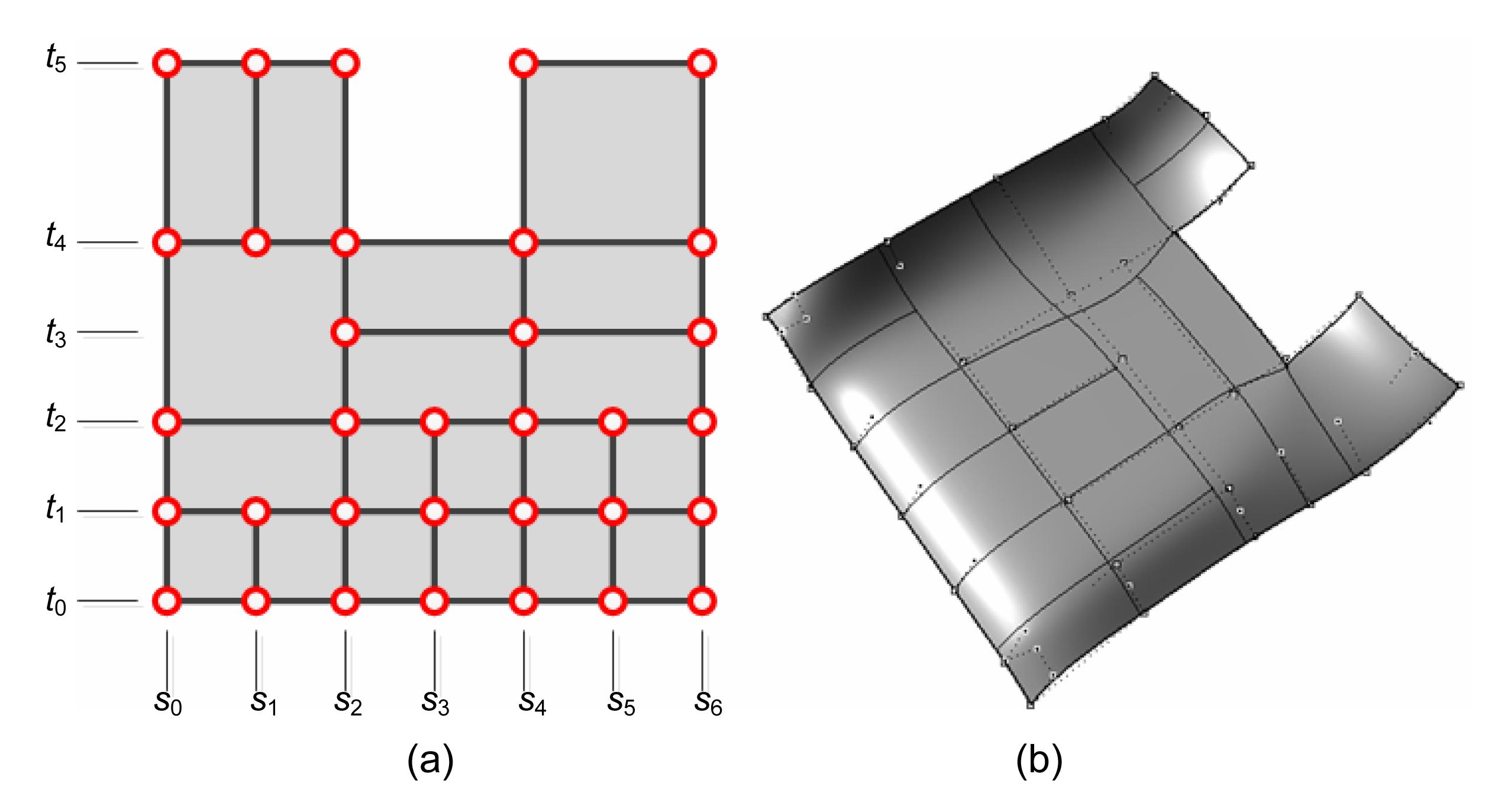
Similar to tensor-product NURBS, T-spline is also defined on a control grid, called a T-mesh. Control vertices in the T-mesh correspond to knots in a parametric pre-image. A typical T-spline surface model is given in Fig. 3. Fig. 3a shows the pre-image while the T-mesh and the surface are shown in Fig. 3b. The main differences between the T-spline and the tensor-product NURBS are shown in the pre-image. In the T-spline, the number of knots in every row and column is not necessarily the same. The interrupted knot resembles the capital letter T, hence the term T-spline. Moreover, every knot has a dominating area and exerts influence on points under its domination. For degree d (order d+1), knot vectors si=[si0, si1, ..., si(d+1)] and ti=[ti0, ti1, ..., ti(d+1)] can be found using the ray shooting method (Sederberg, et al., 2003). The resulting rectangle from (si0, ti0) to (si(d+1), ti(d+1)) is called the domain of the knot. Taking the bi-cubic case for example, as shown in Fig. 3, to find the knot vector for knot [s4, t2], rays shoot two bays in four directions, namely +s, −s, +t and −t. The resulting knot vectors are [s2, s3, s4, s5, s6] and [t0, t1, t2, t3, t4].
Fig.3 A simple T-spline surface (a) Pre-image of T-spline surface; (b) T-spline surface with controlling T-mesh
Definition 1 Given a 2D T-spline pre-image, the position of a surface point can be retrieved by inputting parameter (s, t) to:
,
where Pij is the control vertex and Wij is the corresponding weight. Taking the t-direction for example, the B-spline base function N(t) is recursively defined as
As a bi-cubic T-spline is used in this work, the subscript d=3 is not written later on. Excellent properties of piecewise base function are inherited in T-spline surface, including partition of unity, pointwise nonnegative, affine covariance, and convex hull property.
Definition 2 If we merge some of the terms in Eq. (1), the T-spline surface can be seen as the linear combination of NURBS curves
,
where an NURBS curve is .
If column vectors and represent the collections of base functions and curves respectively, the matrix form of Eq. (2) can be derived
.
Such a definition is useful in T-spline fitting and skinning, as will be mentioned in the following section. From another point of view, Eq. (2) can be further simplified.
Definition 3 Given a T-spline surface with b control vertices and denoting the product of B-spline base functions in two directions as the blending function , the T-spline surface can be expressed by .
If we denote the rational blending function with weight as , then the above surface function can be rewritten as .
We can also define the matrix form:
,
where the column vectors and denote rational blending functions and control points, respectively. This definition clearly shows the advantages of the T-spline surface. It does not have the limitations of the tensor-product definition. Given a parametric knot coordination [s, t] the corresponding surface point S(s, t) is expressed as a linear combination of control vertices. The coefficient of each vertex is the value of a rational blending function, denoting the influence that it contributes to the surface point.
3.2. Skinning from bone data point
The abovementioned properties of T-spline make it an ideal model for reverse engineering, especially in point cloud fitting. Different surface reconstruction methods for the T-spline have been proposed in (Wang et al., 2011). For revolving parts with data points arranged along the directrix, the skinning method is suitable and promising. We therefore use the skinning method of Yang and Zheng (2012) to construct the finger bone surface.
The goal can be stated as shown in Fig. 4: given a series of data points arranged in 17 rows and 100 data points for each row, to loft a T-spline surface according to Eq. (2) while keeping the least number of control vertices within the error tolerance e.
Fig.4 Middle bone finger surface skinning from data points (a) Original data points; (b) B-spline curves fitting from data points; (c) Final T-spline surface lofted from control curves
First, each of the 17 rows of data points are interpolated by a B-spline curve Cj(s). The resulting curves can be seen as the sectional curves of the bone surface.
Second, according to Eq. (3), a T-spline surface S(s, t) is interpolated from curve Cj(s) i.e.,.
In order to find control curves Q, which are linear combinations of the sectional curves, a process of solving inverse matrix is carried out according to the method of Yang and Zheng (2012). After that, 19 control curves are found.
Finally, in order to simplify the control curves Qj(s) with fewer control vertices and knots, we construct a curve with initial knot vector . Given a fitting error limit of e, we continually check the distance between the approximated curves and the original ones at sample points. If , the corresponding original knot s will be included in the knot vector . In this way, new control curves are constructed with the most economical number of control vertices.
As a result, a desired T-spline surface with 278 control vertices is found. It can be readily used for morphing machining as follows.
4. Morphing machining of artificial bone
4.1. Algorithm overview
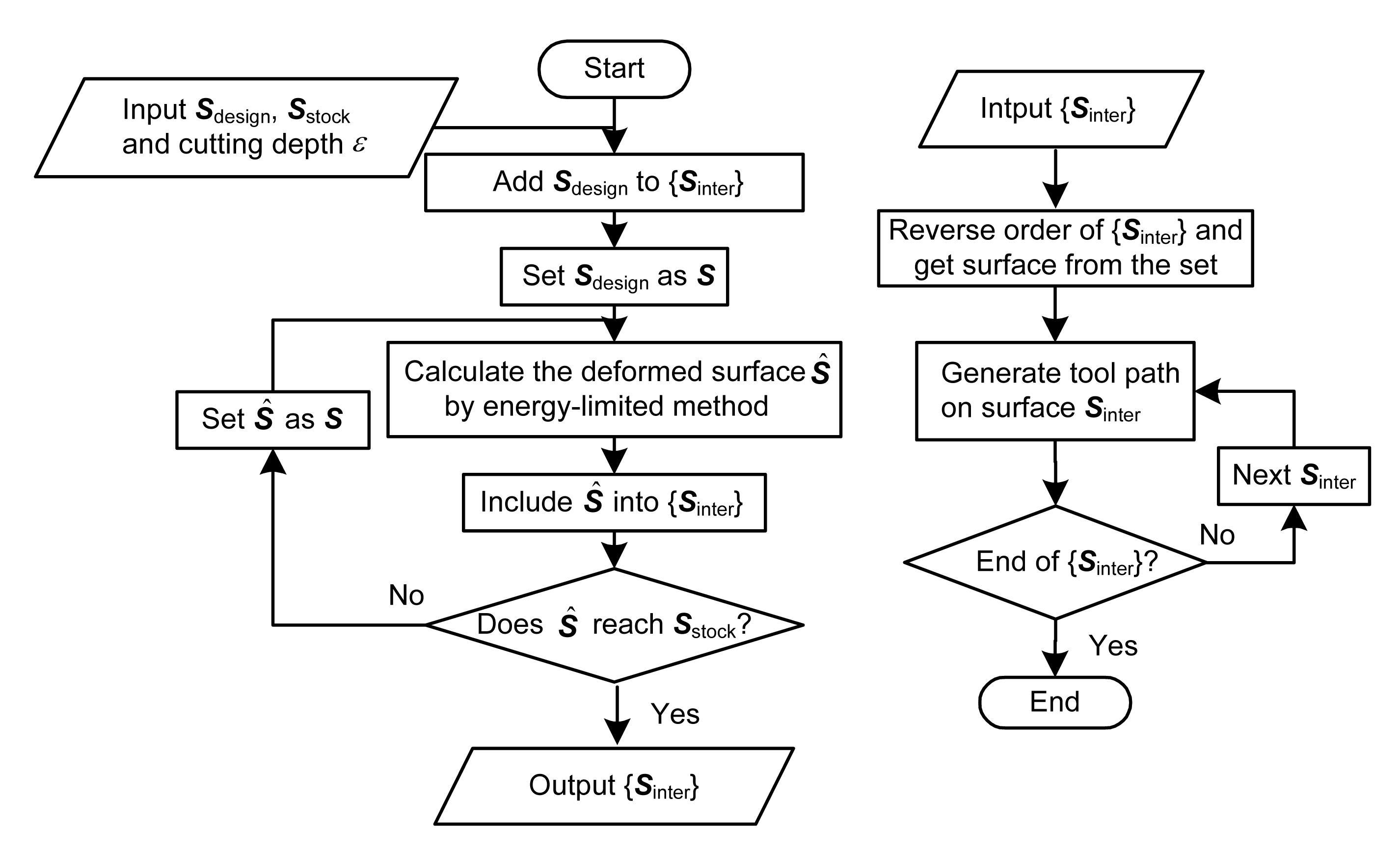
The aim of MMS is to take advantage of surface morphing technique. For a predefined design surface Sdesign represented in a T-spline formula, we conduct a series of morphing processes to transform it gradually into the stock surface Sstock. The interval surfaces between Sdesign and Sstock are denoted as . Tool path planning is conducted on each Sinter to produce a series of cutter contact (CC) and cutter location (CL) paths. Finally, in the actual machining, a reversed ordering is used. The machining procedure is started from a level near Sstock to that near Sdesign. As a result, the workpiece is progressively machined and the final shape gradually comes into being. A complete flowchart of the proposed method can be seen in Fig. 5.
Fig.5 Complete flowchart of the proposed MMS
Two issues should be taken into serious consideration in the MMS process. First, in what manner does the surface deform from one level to the next. Second, how do we plan tool paths on each level. The abovementioned issues will be covered below.
4.2. Energy-minimization morphing of control vertices
Let us first consider one deformation process. The surface before deformation is denoted as S and the deformed surface as . According to Eq. (4), surfaces S and possess the same T-mesh structure while they are different geometrically. It means that surface deformation is represented by the change in control vertices. Assuming the new control vertices to be , we can obtain the following definition.
Definition 4 Surface after one deformation process can be expressed by , where are the perturbations compared with original vertices .
Based on such a definition, an energy-based dynamic evolution model can be constructed. The objective is to minimize the surface energy during deformation between each two levels, and determine the new control vertices .
Definition 5 The total energy consists of two portions, the inner energy of the surface Eint and its external energy Eext:
,
where Eext is the main stimulation of deforming. Eint can be seen as the unevenness of surface.
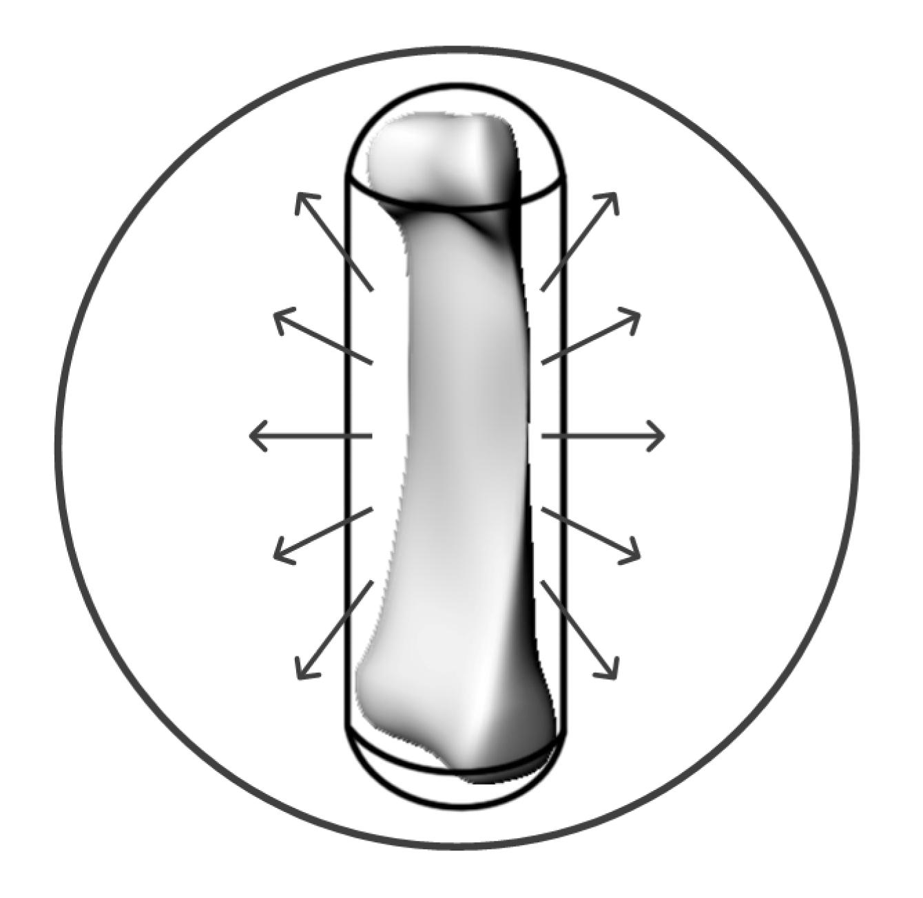
The external potential energy for deformation comes from the attraction to the source. In this work, the source of the attraction force is a bounding sphere H centered at the middle of the bone surface, as shown in Fig. 6. is the coefficient of the attraction force. For a point on the deformed surface, it has a potential energy with regard to its distance from the attraction source. The energy is .
Fig.6 Surface attracted by the bounding sphere Arrows indicate the direction of attraction force
On the other hand, according to (Terzopoulos et al., 1988), a deformable surface is analogous to an elastic sheet plate. The inner energy is defined by the second fundamental forms , , and . They represent the two directional bending and twisting potentials, respectively. Thus, the inner energy of T-spline surface is given by
,
where the superscript indices denote partial derivatives, i.e., , and so on. cint is the coefficient of the internal energy.
Substituting Eqs. (6) and (7) into Eq. (5) yields:
,
In actually solving Eq. (9), the integral form cannot be solved analytically. Discretization can be employed. Suppose r data points are sampled from the surface S. Without causing ambiguity, the subscript l denotes the different sampling points on the surface, i.e., , , and . l automatically runs or sums to r. By converting continuous integration to discrete summarization, Eq. (9) can be written as
Next, the constraints of surface deform should be defined considering the machining parameters for later tool path planning process.
Definition 6 The constraints of surface deform have two parts. First, the distance between and S is constrained by cutting deep ε, i.e.,.
By sampling points on surface, it yields
.
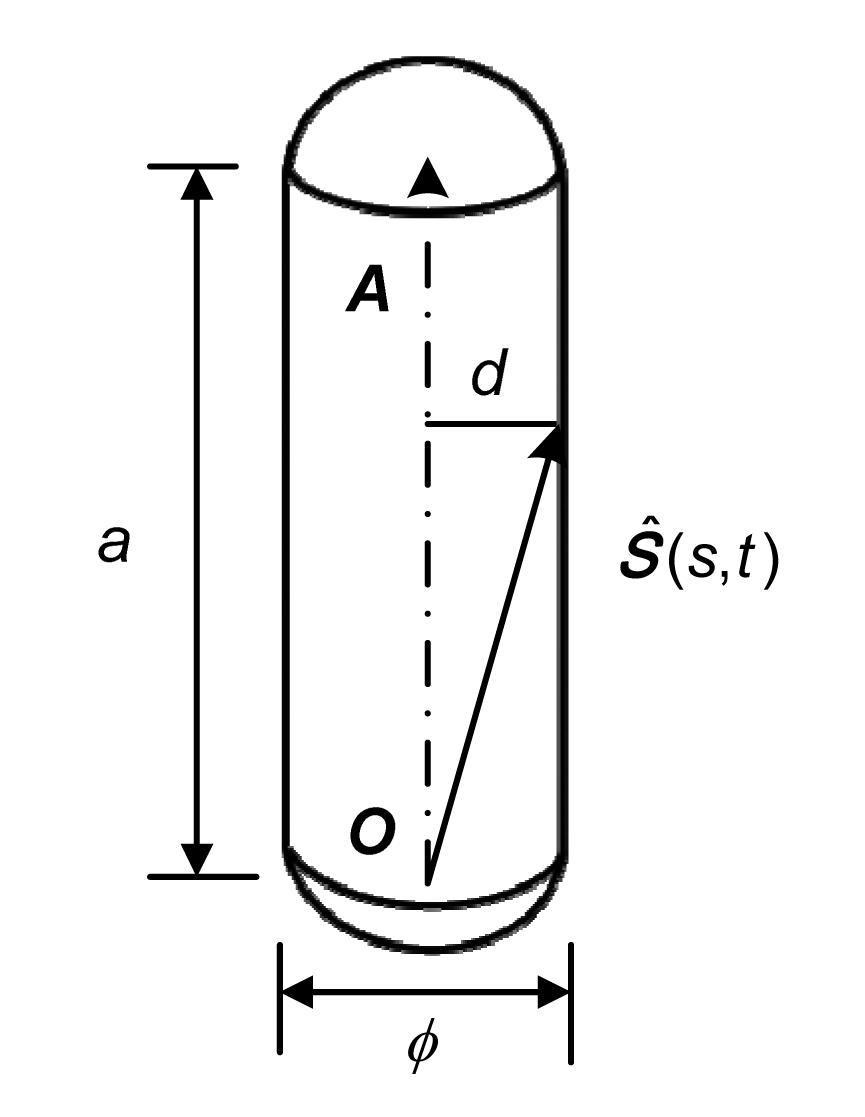
Second, the upper bound is constrained by the stock surface. Suppose the middle axis is a line segment starting from O with direction vector A and length a. As shown in Fig. 7, the distance d from a surface point to the middle axis is limited under ., where sign function and denotes the inner product of and A. After discretization, it yields
.
Fig.7 Capsule shape of the stock surface constraint
As implied by the above constraints, a capsule shaped stock is used in our work. Originally, a cylinder stock such as aluminum bar was used. Nevertheless, creases on both top and bottom end faces may affect the cutting conditions and accelerate tool wear. A capsule stock will therefore be more suitable for MMS. Finally, we propose the following argument.
Argument The process of deformation is de facto a quadratic constrained quadratic optimization (QCQO) problem.
Proof From Eqs. (8), (11), and (12), the goal of the deformation process can be stated as: to find the 278 control vertices in while minimizing: , s.t.,.
The quad matrix M, linear matrix N, and constant L are calculated by Eq. (10). Because of the non-negative property of the B-spline base function, the quad matrix M would be positive semi-definite. The problem can be solved using the extended Euler-Lagrange equation with Karush-Kuhn-Tucker (KKT) conditions. In practice, we employ quadratic constrained quadratic programing (QCQP) in CVX (Grant and Boyd, 2008; 2012) for Matlab to solve the problem.
4.3. On-level tool path scheduling
Several algorithms can be applied to on-level tool path planning. For a revolving artificial bone surface, the simple yet effective scallop-limited zig-zag strategy (Suresh and Yang, 1994) is employed. Given the scallop height limit of h, a constant scallop tool path can be calculated by the following steps: suppose denotes the set of all paths in parametric space.
Step 1: take the left boundary of parametric space, i.e., s=0, as the starting line and include it into {T}. Sample it with regard to forward-step limitation.
Step 2: for every sample point, calculate its side-step S in the direction perpendicular to the feed direction, as shown in Fig. 8. Rcutter is the radius of cutter, and Rsurface is the surface curvature radius in the corresponding direction. Then calculate the difference between the side-step point and the sample point in parametric space using Eqs. (13) and (14). ,
,
where E, F, and G are the first fundamental forms of the surface.
Step 3: choose the smallest Δs. If s+Δs is over the right boundary, then include the right boundary into {T} as the final line and go to the next step. If not then set s=s+Δs as the current line and repeat Step 2.
Step 4: link the iso-parametric lines in a pre-image and map them to Euclidean space. The zig-zag path is thus constructed.
Fig.8 Side-step calculation under scallop limit
5. Experiments
5.1. Computer simulation
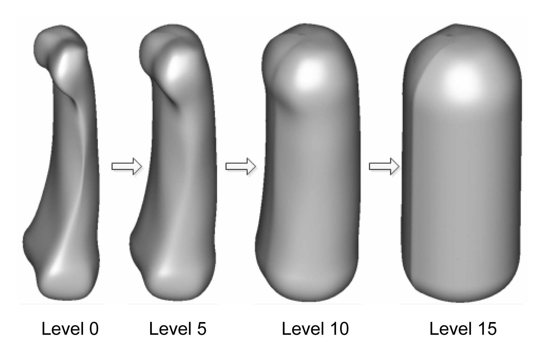
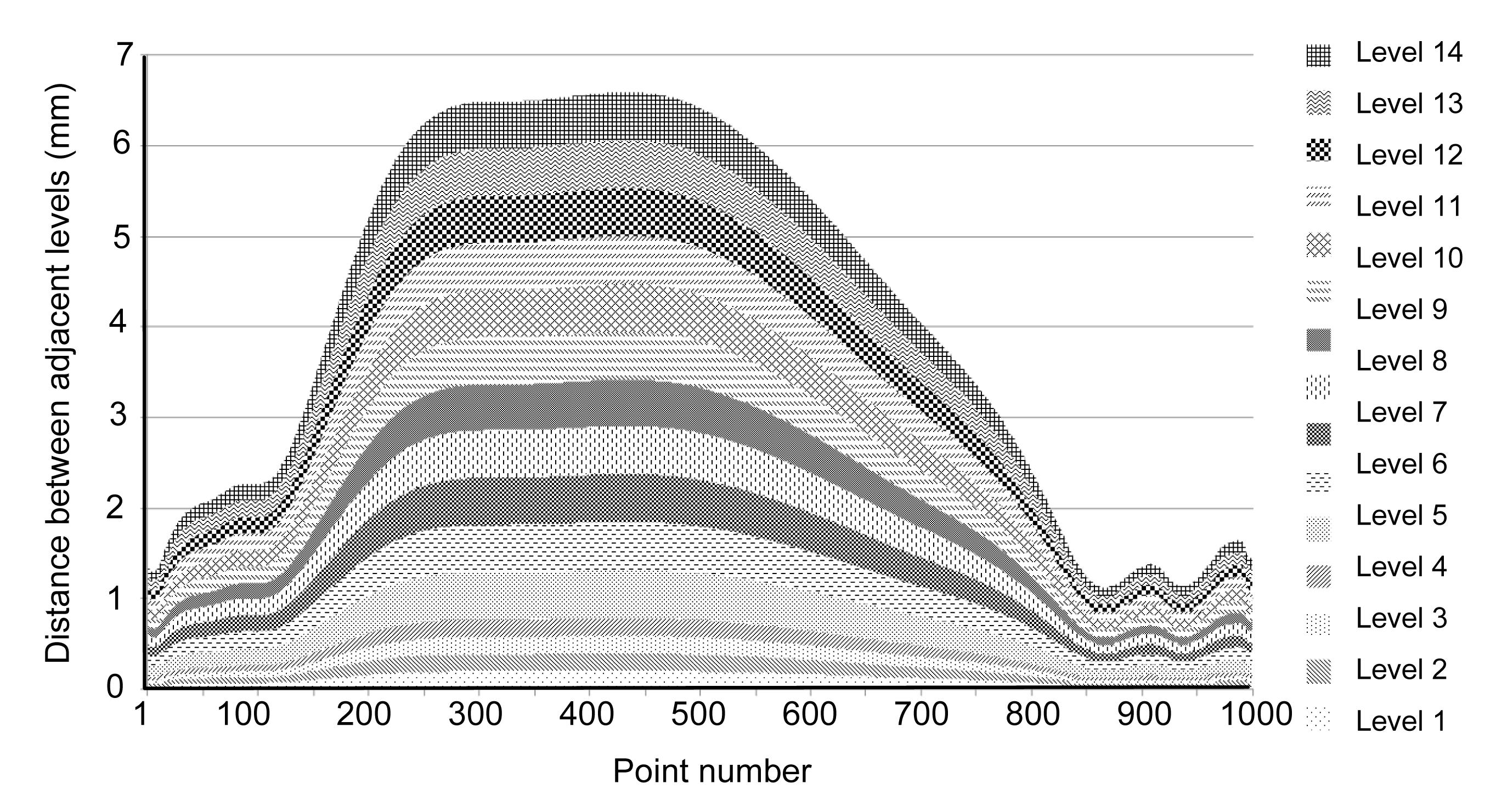
The cutting depth is set to be 0.1 mm for the first four levels and 0.5 mm for the rest, indicating that the machining of levels 0, 1, 2, and 3 is a final finishing, while the others are a roughing process. It takes a totally 16 levels to completely deform from design surface to the stock surface, including level 0 as Sdesign and level 15 as Sstock. In Fig. 9, the rendered views of levels 0, 5, 10, and 15 are listed. A sectional view of the accumulation of all internal surfaces rendered in different colors is shown in Fig. 10. One can clearly see the morphing of the design surface to the stock surface. In order to examine whether the internal surface points are changing as we suppose, 1000 points are sampled from parametric curve s=0.7. The distances of each point on the sequential surface are displayed in Fig. 11. Because of the special shape of the bone, points in the middle section (points numbered from 300 to 500) have experienced larger changes. Most of their distances reach the predefined cutting depth limits of the current level. On the other hand, for points around the top and the bottom (near the joint), changes are relatively small. For example, the total position change of point No. 900 is only about 1 mm, far less than that of points in the middle section.
Fig.9 Morphing of T-spline surface
Fig.10 Profile view of all levels Points are sampled from the parametric curve s=0.7 for cutting depth analysis
Fig.11 Sampled point distances on adjacent levels
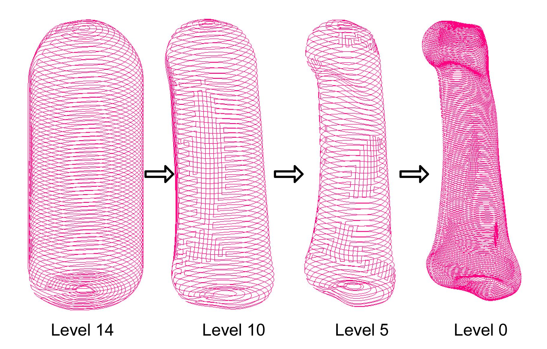
Once the internal surface series is generated, tool path generation is conducted on each internal surface, as shown in Fig. 12. As mentioned above, the first three levels are considered as the finishing process. A ball end tool of radius 1 mm is employed and the scallop height limit is set to be 0.01 mm. On the other levels, a ball end tool of radius 2 mm is chosen and the scallop limit is looser and is set to be 0.05 mm. A bigger scallop height results in a larger side-step and thus a shorter tool path. This will be useful for quickly removing materials from the stock.
Fig.12 Tool path on each level
5.2. Actual machining
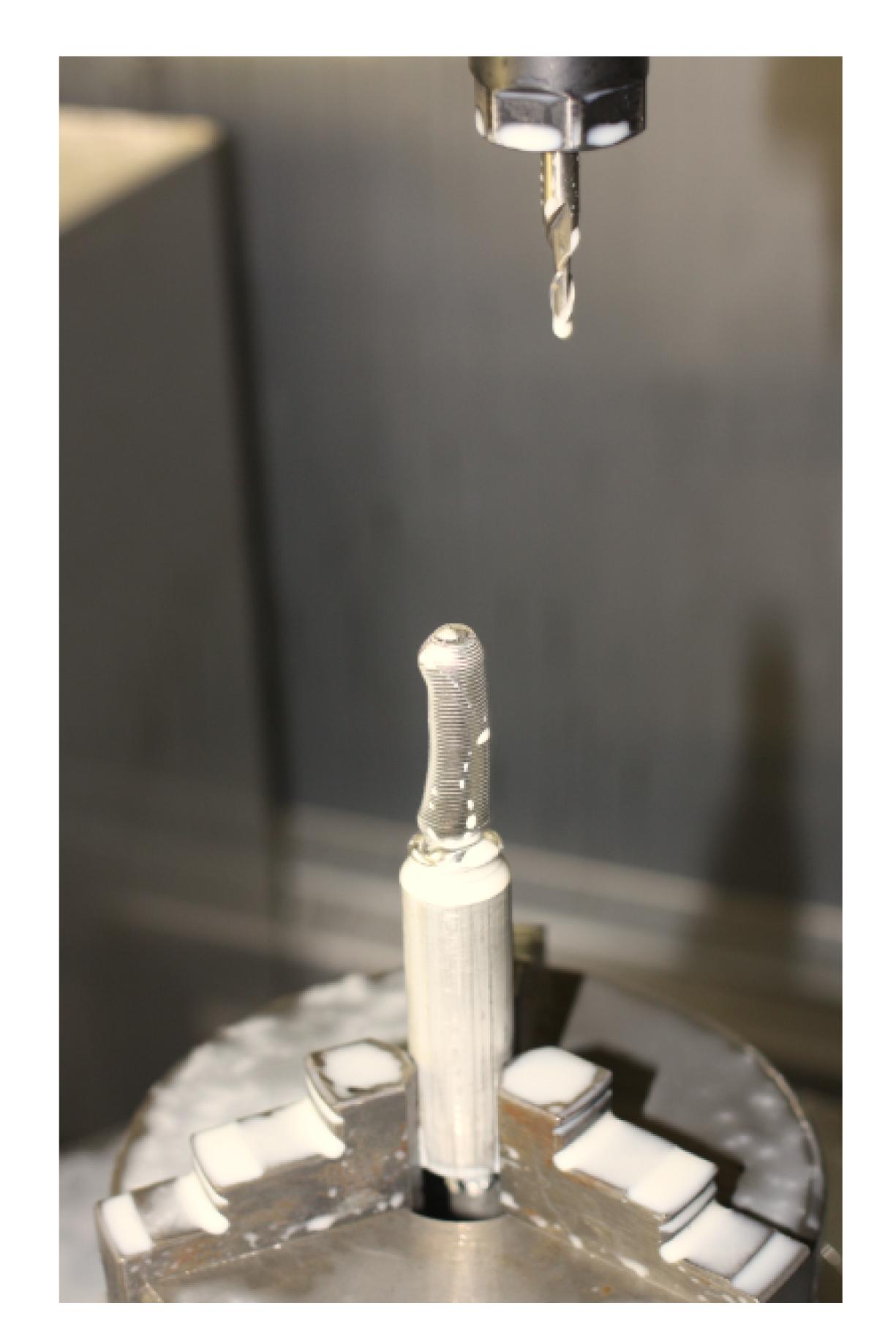
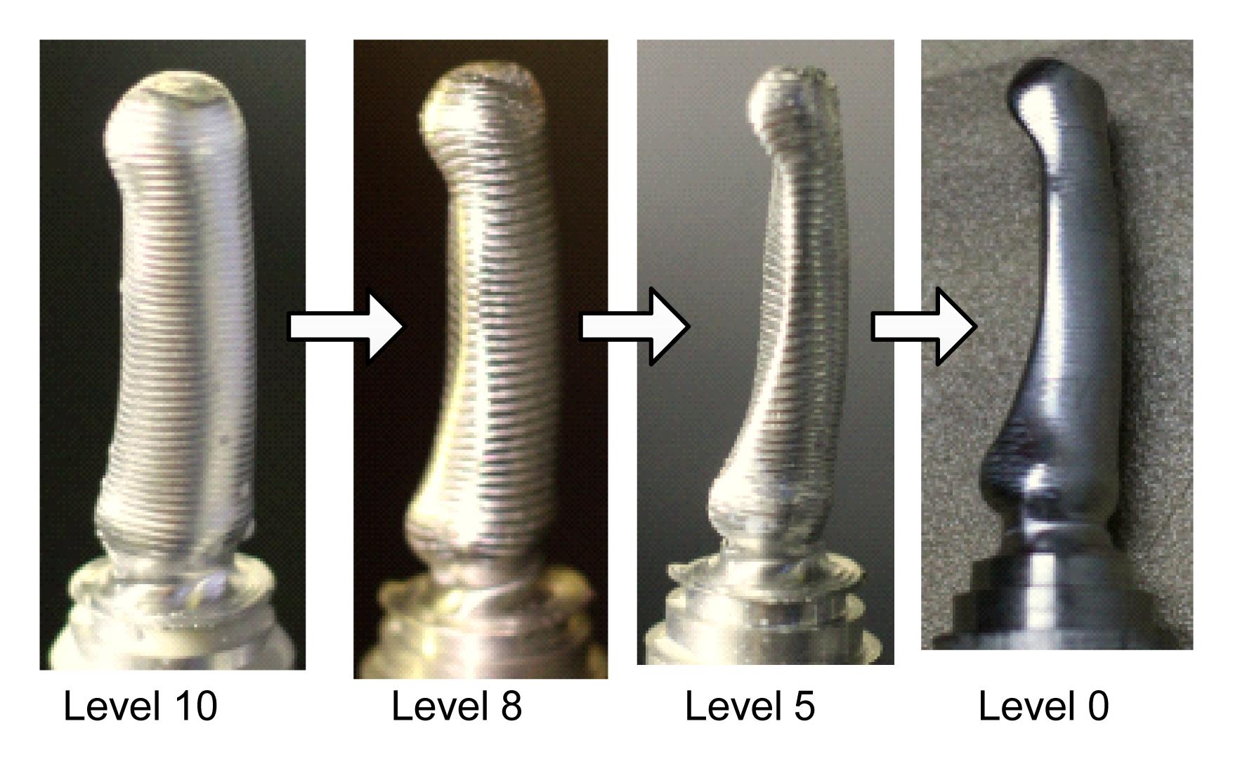
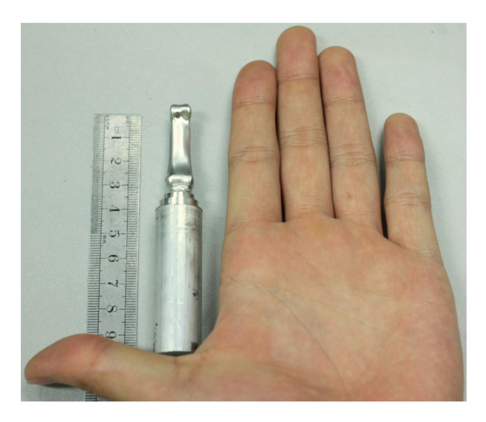
Actual machining was conducted on a Mikron UCP 600 five-axis machining center with Heidehain 530 CNC system embedded. Machining parameters were set as: spindle speed 4500 r/min, feed rate 900 mm/min. The incline angle was set to 10°, a common practice in industry to avoid the zero-cutting speed tool tip. The artificial finger bone was cut from a stock of aluminum-alloy cylinder, 15 mm in diameter, and 37 mm in height (with the extra length for holding excluded), as shown in Fig. 13. As mentioned above, the stock was first rounded to a capsule shape. Then, we actually implemented the proposed MMS on the part. A total of 15 traverses were taken to gradually carve out the final shape of the middle finger bone. The machined surface after levels 10, 8, 5, and 0 are shown in Fig. 14. The finished part is shown in Fig. 15.
Fig.13 Artificial finger bone model being machined
Fig.14 Machined surface on each level
Fig.15 Finished artificial finger bone part
5.3. Comparison study
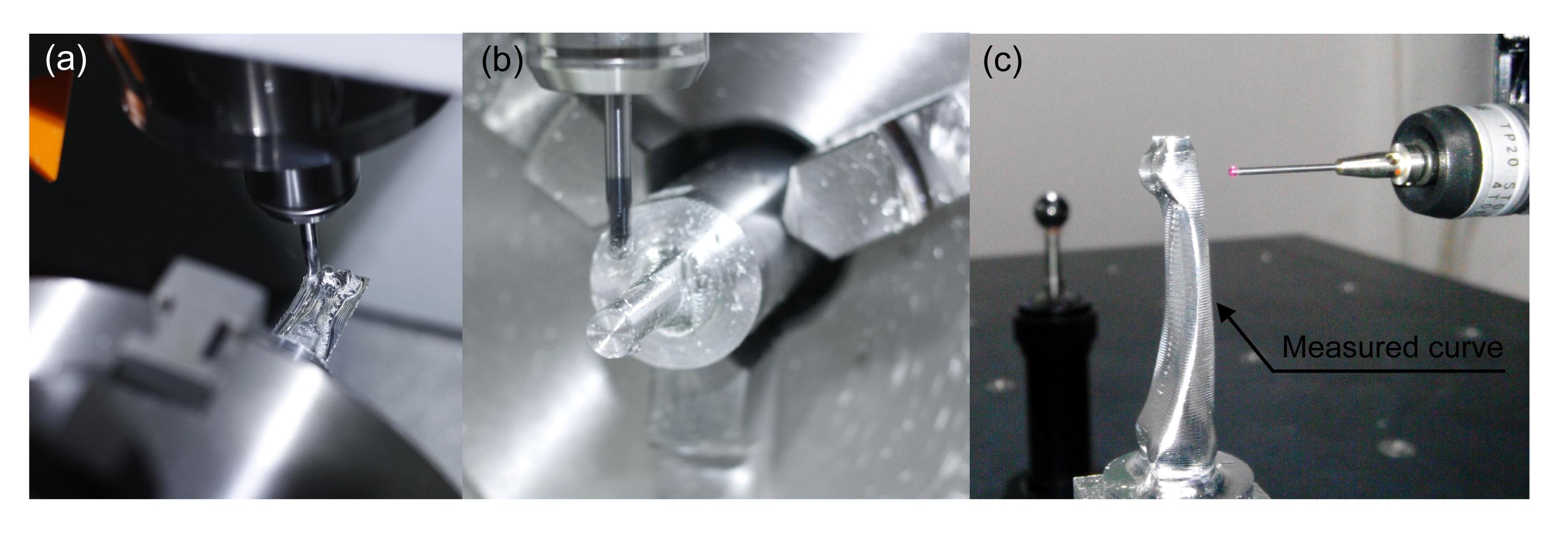
To demonstrate the advantage of the proposed algorithm, a comparative study was conducted with the other two traditional machining strategies: iso-height milling and sectional rotary milling. All workpieces were machined and tested on the coordinate measuring machine (CMM) using a RENISHAW probe with a ruby diameter of 1 mm, as shown in Fig. 16c. A series of 100 points were sampled from the measured curve which lies on the back of the artificial bone. The curve was chosen such that it can represent the surface quality, and showed the shape deflection of the artificial bone as well.
Fig.16 Comparative study (a) Layer-by-layer machining of the bone model using iso-height strategy; (b) Rotary machining of the bone model; (c) Workpiece being measured on a CMM machine
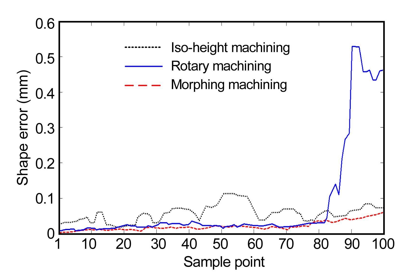
In iso-height machining, the workpiece is first fixed to a certain angle. Then, the tool sweeps over the stock in a layer-by-layer fashion (Fig. 16a). It is sometimes called Z-level machining because the tool stays at the same Z-direction height during layer cutting. After the materials of the current layer are removed, the tool moves down to next layer. Because of the special shape of the artificial bone, iso-height machining on only one side is not enough to fully produce the shape. As a result, when one side of the bone is finished, the bone is turned over to the other side and the layer-by-layer process is repeated. The main advantage of iso-height milling is the speed. This is because during the iso-height machining, rotational axes are not coupled. Only the three linear axes are working. The feed rate can be tuned up to a high level. However, the disadvantage is also apparent. First, because of the special shape of artificial bone and the nature of iso-height milling, the cutting depth of each layer varies from 0 to the layer height. The cutting tool sometimes encounters materials while at other times no cutting operation takes place. The sudden change of cutting depth not only leaves cutting tracks on the bone surface, but also leaves a stair-case of uncut material between layers, as shown in Fig. 17a. As can also be seen in Fig. 18, the shape error curve of an iso-height machined part exhibits fluctuating waves because of the uncut materials. Moreover, the bone is machined on one side after the other. When machining the second side, the uneven cutting depth on the second side exerts a great impact on the slender workpiece. Now that the first side is already finished, little material is left on the surface to support the bone. As a result, the bone deflects to the first side and behaves as a typical cantilever beam.
Fig.17 Comparison between three machining strategy (a) Workpiece produced by iso-height machining with uneven traces between layers; (b) Workpiece produced by rotary machining with material left over on top of the bone; (c) Workpiece produced by MMS
Fig.18 Shape error of the three workpieces
Sectional rotary milling is similar to a lathing process to a certain extent (Fig. 16b). During the process, the part keeps turning around its pivot while the tool feeds from the radial direction. Nevertheless, different from the lathing process, the cutting force is not generated by high speed turning of a workpiece, but the self-turning of the tool. As a result, rotary milling can produce workpiece with non-perfect revolved parts. The advantage of sectional rotary milling is that it performs better in maintaining the straightness of a slender workpiece (Fig. 18). However, this method can only handle the outer surface in the radial direction and leaves the end of the workpiece unmachined. As shown in Fig. 17b, raw materials are left over near the top of the artificial bone. Significant shape error is thereby introduced.
Compared with the other two strategies, MMS produces a better workpiece. No uncut occurs between layers or on the top of the bone, resulting in a better surface quality, as shown in Fig. 17c. Moreover, due to the evenly distributed cutting depth, the cutting force remains stable all through the machining process. No sudden impact is exerted on the part. As a result, the shape deviation of the artificial bone is limited to less than 0.05 mm.
6. Conclusions and future work
In this work, five-axis machining is employed to manufacture a model of an artificial finger bone.
An integrated artificial bone fabrication procedure based on T-spline surface is proposed. The merits of T-spline in surface regeneration are fully exploited. The simple and flexible topological structure is useful in reconstructing the complex and irregular shape of the artificial bone surface. Then, the bone model is easily prepared for the machining process. This work is the first attempt to apply T-spline in medical care.
An energy-based surface morphing method for T-spline surface is developed. By minimizing the internal and external energy, new vertices of the surface are calculated. The surface gradually deforms towards the target surface.
Based on the morphing algorithm, a novel morphing machining strategy for artificial finger fabrication is proposed. Machining parameters such as cutting depth and the bounding of stock are taken into consideration and serve as deforming constraints. Computer simulation and actual machining results show that cutting depths are smoothly distributed over levels. The proposed method is perfectly suitable for a slim workpiece of the size of a finger bone.
The disadvantage of the proposed strategy is clear. On every level, the tool has to cover the whole internal surface. For our example, every one of the 15 internal surfaces (except the stock surface) is machined. At some positions, the actual cutting depth of the tool is far less than the given limitation, as can be seen in the places near the top and the bottom areas of the finger bone model. The tool traversing on these areas is of low efficiency.
Moreover, in this work, only an ordinary T-spline surface is taken into consideration. T-spline with abnormal control vertices, referred to as non-uniform rational Catmull-Clark surfaces with T-junctions (T-NURCC), has recently received enormous research interest. Yet, neither its application in medical area nor the deformation technique of T-NURCC has been fully exploited. Another new extension of T-spline, the PHT, has also aroused huge attention. Compared with T-spline, its topological structure is more flexible. Moreover, its basis function is polynomial instead of rational, allowing simpler computation for surface evaluation, knot insertion, and local refinement. However, research on CAM on the above-mentioned new surfaces has not yet been explored. These related studies should also be part of future works.
[2] Bazilevs, Y., Calo, V.M., Cottrell, J.A., 2010. Isogeometric analysis using T-splines. Computer Methods in Applied Mechanics and Engineering, 199(5-8):229-263.
[3] Botsch, M., 2008. On linear variational surface deformation methods. IEEE Transactions on Visualization and Computer Graphics, 14(1):213-230.
[4] Chen, W., Li, Y., Zheng, J., 2011. T-splines in VRML. , Proceedings of the 10th International Conference on Virtual Reality Continuum and Its Applications in Industry, Hong Kong, China, 257-264. :257-264.
[5] Chen, Y.H., Hu, Y.N., 1999. Implementation of a robot system for sculptured surface cutting. Part 1. Rough machining. International Journal of Advanced Manufacturing Technology, 15(9):624-629.
[6] Chuang, S.H.F., Wang, I.Z., 2000. Multipatched B-spline surfaces and automatic rough cut path generation. International Journal of Advanced Manufacturing Technology, 16(2):100-106.
[7] Da Costa, D.D., Lajarin, S.F., 2012. Comparison of cranioplasty implants produced by machining and by casting in a gypsum mold. International Journal of Advanced Manufacturing Technology, 58(1-4):1-8.
[8] Dai, N., Dong, G.L., Liao, W.H., 2013. Dental restoration contour-parallel offset tool path links based on graph model. International Journal of Advanced Manufacturing Technology, 66(1-4):555-563.
[10] Gaspar, M., Weichert, F., 2013. Integrated construction and simulation of tool paths for milling dental crowns and bridges. Computer-Aided Design, 45(10):1170-1181.
[11] Giannatsis, J., Dedoussis, V., 2009. Additive fabrication technologies applied to medicine and health care: a review. International Journal of Advanced Manufacturing Technology, 40(1-2):116-127.
[12] Grant, M., Boyd, S., 2008. Graph implementations for nonsmooth convex programs. Recent Advances in Learning and Control. Springer,London :95-110.
[13] Grant, M., Boyd, S., 2012. CVX: Matlab Software for Disciplined Convex Programming, Version 2.0 beta. , Available from
http://cvxr.com/cvx,[Accessed on March 2013],:
[14] He, J.K., Li, D.C., Lu, B.H., 2006. Custom fabrication of a composite hemi-knee joint based on rapid prototyping. Rapid Prototyping Journal, 12(4):198-205.
[15] Hu, S.M., Li, Y.F., Ju, T., 2001. Modifying the shape of NURBS surfaces with geometric constraints. Computer-Aided Design, 33(12):903-912.
[16] Hu, Y.N., Tse, W.C., Chen, Y.H., 1998. Tool-path planning for rough machining of a cavity by layer-shape analysis. International Journal of Advanced Manufacturing Technology, 14(5):321-329.
[17] Kim, H.C., 2010. Tool path generation for contour parallel milling with incomplete mesh model. International Journal of Advanced Manufacturing Technology, 48(5-8):443-454.
[18] Kim, H.C., Yang, M.Y., 2008. Incomplete mesh-based tool path generation for optimum zigzag milling. International Journal of Advanced Manufacturing Technology, 35(7-8):803-813.
[19] Lauwers, B., Lefebvre, P.P., 2006. Five-axis rough milling strategies for complex shaped cavities based on morphing technology. CIRP Annals-Manufacturing Technology, 55(1):59-62.
[20] Lian, Q., Li, D.C., Tang, Y.P., 2006. Computer modeling approach for a novel internal architecture of artificial bone. Computer-Aided Design, 38(5):507-514.
[21] Lin, Z., Fu, J., He, Y., 2013. A robust 2D point-sequence curve offset algorithm with multiple islands for contour-parallel tool path. Computer-Aided Design, 45(3):657-670.
[22] Luo, Y.X., He, K., Du, R.X., 2010. A new sheet metal forming system based on the incremental punching, part 1: Modeling and simulation. International Journal of Advanced Manufacturing Technology, 51(5-8):481-491.
[23] Moore, P., Molloy, D., 2007. A survey of computer-based deformable models. , Proceedings of the International Machine Vision and Image Processing Conference, IEEE Computer Society, 55-66. :55-66.
[24] Nguyen-Thanh, N., Kiendl, J., Nguyen-Xuan, H., 2011. Rotation free isogeometric thin shell analysis using PHT-splines. Computer Methods in Applied Mechanics and Engineering, 200(47-48):3410-3424.
[25] Nguyen-Thanh, N., Nguyen-Xuan, H., Bordas, S.P.A., 2011. Isogeometric analysis using polynomial splines over hierarchical T-meshes for two-dimensional elastic solids. Computer Methods in Applied Mechanics and Engineering, 200(21-22):1892-1908.
[26] Porter, J.R., Ruckh, T.T., Popat, K.C., 2009. Bone tissue engineering: a review in bone biomimetics and drug delivery strategies. Biotechnology Progress, 25(6):1539-1560.
[27] Sarkar, S., Dey, P., 2013. Tool path generation for algebraically parameterized surface. Journal of Intelligent Manufac-turing, :1-7.
[28] Sederberg, T.N., Zheng, J.M., Bakenov, A., 2003. T-splines and T-NURCCs. ACM Transactions on Graphics, 22(3):477-484.
[32] Su, X.B., Yang, Y.Q., Yu, P., 2012. Development of porous medical implant scaffolds via laser additive manufacturing. Transactions of Nonferrous Metals Society of China, 22:S181-S187.
[33] Su, X.B., Yang, Y.Q., Xiao, D.M., 2013. An investigation into direct fabrication of fine-structured components by selective laser melting. International Journal of Advanced Manufacturing Technology, 64(9-12):1231-1238.
[34] Suresh, K., Yang, D.C.H., 1994. Constant scallop-height machining of free-form surfaces. Journal of Engineering for Industry-Transactions of the ASME, 116(2):253-259.
[35] Terzopoulos, D., Witkin, A., Kass, M., 1988. Constraints on deformable models: recovering 3D shape and nonrigid motion. Artificial Intelligence, 36(1):91-123.
[36] Wang, W.Y., Zhang, Y.J., Scott, M.A., 2011. Converting an unstructured quadrilateral mesh to a standard T-spline surface. Computational Mechanics, 48(4):477-498.
[37] Wu, W.Z., Zhang, Y., Li, H., 2009. Fabrication of repairing skull bone defects based on the rapid prototyping. Journal of Bioactive and Compatible Polymers, 24(suppl.1):125-136.
[38] Xu, J.H., Zhang, S.Y., Tan, J.R., 2013. Collisionless tool orientation smoothing above blade stream surface using NURBS envelope. Journal of Zhejiang University-SCIENCE A (Applied Physics & Engineering), 14(3):187-197.
[39] Yang, H.P., Juttler, B., 2007. 3D shape metamorphosis based on T-spline level sets. Visual Computer, 23(12):1015-1025.
[41] Zhu, X.F., Hu, P., Ma, Z.D., 2013. A new surface parameterization method based on one-step inverse forming for isogeometric analysis-suited geometry. International Journal of Advanced Manufacturing Technology, 65(9-12):1215-1227.
Open peer comments: Debate/Discuss/Question/Opinion


Open peer comments: Debate/Discuss/Question/Opinion
<1>
1@11<12@12.df>
2014-03-28 15:15:36
it is a good paper,recommend!!
amisan@12<12@12.df>
2014-03-28 14:53:20
In this work, a novel morphing machining strategy (MMS) is proposed. It is a good paper.