Affiliation(s):
1.
College of Civil Engineering and Architecture, Zhejiang University, Hangzhou 310058, China; moreAffiliation(s): 1.
College of Civil Engineering and Architecture, Zhejiang University, Hangzhou 310058, China; 2.
Deptment of Civil and Environmental Engineering, University of Alberta, Edmonton, AB, T6G 2W2, Canada; less
Shuai Guo, Tu-qiao Zhang, Wei-yun Shao, David Z. Zhu, Yuan-yu Duan. Two-dimensional pipe leakage through a line crack in water distribution systems[J]. Journal of Zhejiang University Science A, 2013, 14(5): 371-376.
@article{title="Two-dimensional pipe leakage through a line crack in water distribution systems", author="Shuai Guo, Tu-qiao Zhang, Wei-yun Shao, David Z. Zhu, Yuan-yu Duan", journal="Journal of Zhejiang University Science A", volume="14", number="5", pages="371-376", year="2013", publisher="Zhejiang University Press & Springer", doi="10.1631/jzus.A1200227" }
%0 Journal Article %T Two-dimensional pipe leakage through a line crack in water distribution systems %A Shuai Guo %A Tu-qiao Zhang %A Wei-yun Shao %A David Z. Zhu %A Yuan-yu Duan %J Journal of Zhejiang University SCIENCE A %V 14 %N 5 %P 371-376 %@ 1673-565X %D 2013 %I Zhejiang University Press & Springer %DOI 10.1631/jzus.A1200227
TY - JOUR T1 - Two-dimensional pipe leakage through a line crack in water distribution systems A1 - Shuai Guo A1 - Tu-qiao Zhang A1 - Wei-yun Shao A1 - David Z. Zhu A1 - Yuan-yu Duan J0 - Journal of Zhejiang University Science A VL - 14 IS - 5 SP - 371 EP - 376 %@ 1673-565X Y1 - 2013 PB - Zhejiang University Press & Springer ER - DOI - 10.1631/jzus.A1200227
Abstract: In water distribution systems, water leakage from cracked water pipes is a major concern for water providers. Generally, the relationship between the leakage rate and the water pressure can be modeled by a power function developed from the orifice equation. This paper presents an approximate solution for the computation of the steady-state leakage rate through a longitudinal line crack of a water distribution pipe considering the surrounding soil properties. The derived solution agrees well with results of numerical simulations. Compared with the traditional models, the new solution allows assessment of all the parameters that related with leakage including the pressure head inside the pipe, hydraulic conductivity, crack size and its position, and pipe size and its depth.
Darkslateblue:Affiliate; Royal Blue:Author; Turquoise:Article
Article Content
1. Introduction
Water loss from water distribution systems is a worldwide problem. The main sources of water losses include pipe leakage, illegitimate and unmetered uses, and under-registration of water meters, among which the leakage usually makes up a large part (Lambert, 2002; Greyvenstein and Van Zyl, 2007). It is reported that leakage loss can reach as high as 70% of total water losses (WHO, 2001), and the annual leaked water is roughly 32 billion cubic meters that is on the order of 81 billion US dollars worldwide (Thornton, 2002; Kingdom et al., 2006; Walski et al., 2009). Therefore, leakage management will remain an important task for municipal engineers.
One of the major factors that influence leakage rate is the pressure in the distribution system. A conventional physical model that relates the pressure and the leakage rate is the well-known orifice equation, described as
,
where Q is the leakage flow rate, Cd the discharge coefficient, A the orifice area, g acceleration due to gravity, and H the pressure head in the pipe.
Given the important influence of pressure on leakage, the pressure reduction procedure was used as an important tool for leakage management in the last thirty years (Vairavamoorthy and Lumbers, 1998; Lambert, 2001; Araujo et al., 2006; Nicolini et al., 2011). When modeling the pressure-leakage rate relationship in individual water distribution systems, a more general form expression was proposed instead of the orifice equation (Lambert, 2001):
,
where c is the leakage coefficient, and N1 is the leakage exponent. The transformed power function (Eq. (2)) allows direct assessment of the pressure reduction effectiveness on leakage control, for example, if the leakage exponent N1 equals the theoretical value of 0.5, when the pressure is halved, the leakage flow rate will reduce by 29%. However, a lot of field studies from Japan (Lambert, 2001) and UK (Farley and Trow, 2003) have shown that N1 can be much larger than 0.5 and can vary between 0.5 and 2.79.
The mechanism for the deviation of the leakage exponent from the theoretical value of 0.5 is not well understood for its complexity. Van Zyl and Clayton (2007) proposed four factors that may be responsible for the higher leakage exponents including leak hydraulics, pipe material behavior, soil hydraulics and water demand. The effect of leak hydraulics has been researched extensively, and a recent experimental investigation on the influence of different types of leak openings including artificial holes, corrosion holes, longitudinal and circumferential cracks on the leakage-pressure relationship was conducted by Greyvenstein and Van Zyl (2007). Their results confirmed that the value of the leakage exponent had a wide range and can be lower and higher than the theoretical value of 0.5. Cassa et al. (2010) studied the behavior of different pipe materials under pressure using finite element analysis. Their results highlight the important influence of existing cracks on the leakage, and a linear relationship between the leak area and pressure was proposed. A recent work from Ferrante (2012) has extended the results of Cassa et al. (2010) by taking the plastic deformation or viscoelastic effect into consideration.
However, there have been few studies on the influence of the surrounding soil on the leakage (Coetzer et al., 2006). The objective of this work is to present an analytical result for predicting the steady-state leakage through a line crack taking influence of the surrounding soil into consideration. Under some reasonable assumptions, the problem was simplified into a 2D one. In order to simplify the complex boundary conditions, one conformal mapping technique (the Möbius transformation) and a new mathematical method (the equivalent circumference method) were introduced. Consequently, an approximate solution was obtained.
2. Methodology
Pipes of different materials usually fail in certain characteristic ways, depending on their material properties; for example, corrosion holes often occur on the steel and cast iron pipes (Van Zyl and Clayton, 2007), while line cracks are common in asbestos cement pipes. Since the asbestos cement material pipes were widely used in the past in China, pipes with longitudinal type of cracks are frequently seen after excavation. As shown in Fig. 1, we consider a cylindrical water pipe embedded in a semi-infinite aquifer. There is a line crack along the pipe wall. In practice, the longitudinal type of crack usually extends a long distance along the pipe wall. In such cases, the leak process can be approximated as a 2D seepage flow problem. To simplify the problem, the following assumptions are made: (1) the aquifer is fully saturated; (2) the surrounding soil is homogenous and isotropic with a constant permeability; and, (3) leakage is steady-state, i.e., the leaking water is drained off.
Fig.1 A section of water pipe with a line crack embedded in a semi-infinite aquifer
The above simplifications are common in analytical studies, despite the deviations from the real cases. The groundwater table is taken as the reference datum, and a Cartesian coordinate system is obtained. The radius of the water pipe is r, the depth of groundwater table is h, α represents the location of the crack (from the horizontal line to the centerline of the crack), and the open angle of the crack is β. Water flow in saturated soil obeys Darcy’s law, which indicates a linear relationship between the velocity and the hydraulic gradient. By combining the continuity equation and the Darcy’s equation, the leaking water movement in the aquifer will be governed by the following 2D Laplace’s equation (Terzaghi et al., 1996):
,
where φ is the hydraulic head. Above the groundwater table is the atmospheric pressure; therefore, the boundary condition at the groundwater table can be expressed as
.
On the other hand, the hydraulic head at the boundary between the crack and the aquifer equals the sum of the elevation head y, which is from the origin to its downward vertical position and the pressure head from inside pipe. Therefore, the boundary condition at the crack can be expressed as
,
where Pi in the pressure inside the pipe, and γw is the water specific weight. If Eqs. (3)–(5) were solved exactly, then the absolute analytical solution for 2D leakage would be obtained. However, the complex second boundary condition (Eq. (5)) applying at the crack prevents its existence. Therefore, an approximate solution is more reasonable and practical and still has its significance for leakage assessment (Guo et al., 2013). To achieve this purpose, we firstly introduce an equivalent circumference method to simplify the second boundary condition, and then use the Möbius transformation technique to transfer the semi-infinite aquifer into a circular domain.
The principle of the equivalent circumference method is to transfer the line crack into a permeable column which is located at the center of the crack (Fig. 2a), making sure that the perimeter of the circumference of the small circle equals the crack arc length in the 2D plane, which means:
.
Therefore, the called equivalent circumference actually represents equivalent permeable area. Then, translate the origin of the rectangular coordinate system to the center of the conceived circle, a new rectangular coordinate system x′-y′ is constructed, and we have
.
Fig.2 Images in the x′-y′ plain (a) and ξ-η complex plain (b)
Next, we use the Möbius transformation to transfer the semi-infinite aquifer.
A major simplification of the mathematical formulation for problems governed by Laplace’s equation can be achieved using conformal mapping techniques; one such technique is the Möbius transformation (Verruijt and Booker, 2000). It transfers the x′-y′ plane into ξ-η complex plain, using the following form:
, .
This transformation preserves Laplace’s equation, and maps the conceived circle and the horizontal groundwater table onto two concentric circles of radius λ=(h′/r′)−[(h′2/r′2)−1]0.5 and 1, respectively (Fig. 2b). Then, in the ξ-η plane, we can rewrite the governing equation and boundary conditions by polar coordinate into the following forms:
, , .
The general solution for Laplace’s equation in a circular domain is readily obtained (Arfken and Weber, 1995). Substituting the boundary conditions Eqs. (11) and (12) into Eq. (10), we can obtain the approximate solution for leakage through a line crack per unit pipe length as per the following equation:
,
where K is the hydraulic conductivity, and .
Since the open angle of the crack β is small, therefore, λ<<1, , and , then Eq. (13) can be simplified as
.
3. Results and discussion
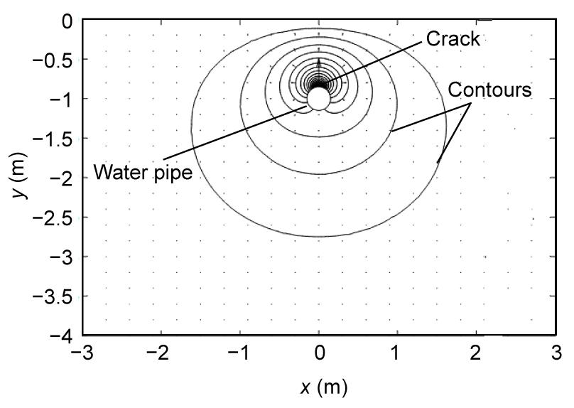
To verify the derived solution, numerical studies were conducted using the partial differential equation (PDE) tool box in MATLAB. The results of the analytical solution and numerical simulations are compared in Table 1; QN represents the numerical result, and QA the analytical value. Cases No. 2 and No. 3 show the influences of pipe radius and crack position on leakage, respectively; Case No. 4 shows the influence of defect opening angle, while Case No. 5 shows the influence of the groundwater table. The flow net for Case No. 2 in the physical domain is given in Fig. 3, where contours are at an interval of 0.01 m, and the water velocity is shown in arrows.
Table 1
Comparison between analytical results and numerical results
Case
h (m)
r (m)
α
β
Pi/γw (m)
Number of elements
QN/K (m)
QA/K (m)
(QA−QN)/QN (%)
No. 1
1
0.10
π/2
π/6
11.1
38 592
0.148
0.117
21
No. 2
1
0.15
π/2
π/6
11.1
36 352
0.202
0.128
36
No. 3
1
0.10
π/4
π/6
11.1
45 632
0.119
0.116
3
No. 4
1
0.10
π/2
π/12
11.1
47 872
0.118
0.104
12
No. 5
2
0.10
π/2
π/6
13.0
43 008
0.741
1.026
38
Fig.3 Flow net around the water pipe with a line crack
As shown in Table 1, the relative differences of analytical and numerical values are less than 40%. Considering the inevitable error in the numerical simulation, the proposed model indicates an acceptable degree of accuracy on estimating leakage rate.
Compared with the highly simplified power function model (Eq. (2)), advantages of the derived analytical expression for steady-state leakage lie in the inclusion of all the parameters responsible for the water lost from leakage including the pressure, the hydraulic conductivity, the crack size and its position, and the pipe size and its depth below the groundwater table.
Lambert (2001) indicated that the crack area can vary with pressure, especially for plastic pipes. This has been numerically and experimentally demonstrated by Cassa et al. (2010), Greyvenstein and Van Zyl (2007) and Ferrante (2012). In their work, different models of leak area and pressure relationship were proposed. These models aim to offer an explanation to the fact that the leakage exponent can be significantly larger than 0.5 according to field studies. However, all these models did not consider the stress effect of the surrounding soil on the pipe wall. If the water pipe keeps in connection with the surrounding soil at the crack, and the boundary between the crack and the soil keeps intact, i.e., soil erosion or piping not happening, the surrounding soil would offer considerable radial and longitudinal stresses against the internal water pressure. Therefore, it can be expected that under steady state leak condition as considered in this study, the pressure and leakage relationship will not be far from a linear relationship, as described by the derived expression (Eq. (14)). This prediction agrees with the test results for the actual water distribution systems, for example, in Japan (averaged N1=1.15) and in UK (averaged N1=1.13) (Lambert, 2001). In fact, Walski et al. (2006) theoretically demonstrated that for a steady-state leakage as considered in this study, the head loss through the soil is much larger than it is through the crack. Burnell and Race (2000) also showed that leakage from supply pipes has a linear correlation to the internal pressure; therefore, the presented linear relationship between pressure and leakage by the new model is reasonable and shows agreement with the test results for actual water distribution systems.
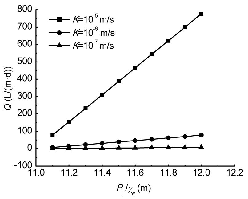
On the other hand, it can be inferred from the derived equation that besides the pressure, hydraulic conductivity is another most important factor on leakage. However, its effect on the leakage rate has not received much attention or any discussion in most of the previous studies. Fig. 4 shows the linear relationship between the hydraulic conductivity and the leakage rate. Parameters are taken as follows in Fig. 4: the radius r=0.1 m, the groundwater depth h=1 m, the line crack locates at the top of the pipe, i.e., α=π/2 and the open angle of the crack β=π/30. The water head inside the pipe Pi/γw has ten different values from 11.1 m to 12 m, and the hydraulic conductivity K has three different values from 10−5 to 10−7 m/s. The leakage rate Q is assessed by unit pipe length per day, i.e., L/(m·d). As shown in Fig. 4, when the cracked pipe is buried under soil with bad permeability, for example, clay soil, which usually has a hydraulic conductivity smaller than 10−7 m/s, the leaked water will be less than several liters one day per unit pipe length. However, if it is buried under soil with good permeability, for example, sandy soil, it will leak approximately 1 ton water one day per unit pipe length.
Fig.4 Effect of hydraulic conductivity on leakage
In actual water distribution networks, the water pressure head inside the pipe can differ significantly over the system. In some pipe segments near the water treatment plant, it can reach as large as 100 m; while in some segments far away from the water treatment plant or under an area with relatively high elevation, it reduces to that only meet the minimum standard, for example 12 m. For the pipe carrying high pressure, once it has any crack, the surrounding soil particles will be fluidized and be quickly washed away by the high pressure water. The hydraulic gradient beyond which the soil will be boiling is known as the critical hydraulic gradient (Terzaghi et al., 1996). The mechanism of this problem is very complex and it is beyond the scope of this paper.
A larger crack will allow larger leakage as shown in Table 1. For a water pipe of radius 0.1 m, and 1 m below the groundwater table, if the area of crack doubles, the leakage rate will increase by about 10%.
The model reveals for the first time that the location of the crack also has an influence on the leakage rate, which has not been noticed by previous researchers. The crack locating on the top of the pipe wall will leak more water as can be seen in Table 1.
4. Conclusions
This paper deals with an approximate solution for calculating the steady-state leakage from water supply pipes with a line crack. Compared with the widely-used power function model, advantages of the new model lie in a much better understanding of parameters that control the leakage rate and a more physical meaning.
In summary, the proposed model is suitable for leakage rate assessment through a long line crack. However, this study is limited to 2D, and some idealized assumptions were introduced, for example, a homogeneous and isotropic aquifer. In addition, the interaction at the boundary between the crack and the surrounding soil needs further investigation, especially under high pressure conditions.
[1] Araujo, L.S., Ramos, H., Coelho, S.T., 2006. Pressure control for leakage minimisation in water distribution systems management. Water Resources Management, 20(1):133-149.
[2] Arfken, G.B., Weber, H.J., 1995. Mathematical Methods for Physicists. Academic Press,New York :
[3] Burnell, D., Race, J., 2000. Water Disstribution Systems Analysis: Patterns in Supply-Pipe Leakage. , Proceedings of ASCE EWRI Conference, Minneapolis, USA, :
[4] Cassa, A.M., Van Zyl, J.E., Laubscher, R.F., 2010. A numerical investigation into the effect of pressure on holes and cracks in water supply pipes. Urban Water Journal, 7(2):109-120.
[5] Coetzer, A.J., Van Zyl, J.E., Clayton, C.R.I., 2006. An Experimental Investigation into the Turbulent-Flow Hydraulics of Small Circular Holes in Plastic Pipes. , 8th Annual Water Distribution Systems Analysis Symposium, Cincinnati, Ohio, USA, :
[6] Farley, M., Trow, S., 2003. Losses in Water Distribution Networks. IWA Publishing,London, UK :
[7] Ferrante, M., 2012. Experimental investigation of the effects of pipe material on the leak head-discharge relationship. Journal of Hydraulic Engineering, 138(8):736-743.
[8] Greyvenstein, B., Van Zyl, J.E., 2007. An experimental investigation into the pressure-leakage relationship of some failed water pipes. Journal of Water Supply: Research and Technology-AQUA, 56(2):117-124.
[9] Guo, S., Zhang, T., Zhang, Y., Zhu, D.Z., 2013. An approximate solution for two-dimensional groundwater infiltration in sewer systems. Water Science and Technology, 67(2):347-352.
[10] Kingdom, W.D., Limberger, R., Marin, P., 2006. The Challenge of Reducing NRW in Developing Countries. , WSS Sector Board Discussion, :
[11] Lambert, A., 2001. What do We Know about Pressure Leakage Relationship in Distribution Systems?. , Proceedings of IWA Specialised Conference: System Approach to Leakage Control and Water Distribution Systems Management, Brno, Czech Republic, 89-96. :89-96.
[12] Lambert, A., 2002. Water losses management and techniques. Water Science and Technology: Water Supply, 2(4):1-20.
[13] Nicolini, M., Giacomello, C., Deb, K., 2011. Calibration and optimal leakage management for a real water distribution network. Journal of Water Resources Planning Management, 137(1):134-142.
[14] Terzaghi, K., Peck, R.B., Mesri, G., 1996. Soil Mechanics in Engineering Practice. )John Wiley & Sons, Inc.,NY, USA :
[15] Thornton, J., 2002. Water Loss Control Management. McGraw-Hill,New York :
[16] Vairavamoorthy, K., Lumbers, J., 1998. Leakage reduction in water distribution systems: optimal valve control. Journal of Hydraulic Engineering, 124(11):1146-1154.
[17] Van Zyl, J.E., Clayton, C.R.I., 2007. The effect of pressure on leakage in water distribution systems. Water Management, 160(2):109-114.
[18] Verruijt, A., Booker, J.R., 2000. Complex Variable Analysis of Mindlin’s Tunnel Problem. , Proceedings of Development of Theoretical Geomechanics, Balkema, Sydney, 3-22. :3-22.
[19] Walski, T., Bezts, W., Posluszny, E.T., Weir, M., Whitman, B.E., 2006. Modeling leakage reduction through pressure control. Journal American Water Works Association, 98(4):147-155.
[20] Walski, T., Whitman, B., Baron, M., 2009. Pressure vs. Flow Relationship for Pipe Leaks. , World Environmental and Water Resources Congress, 1-10. :1-10.
[21] WHO (World Health Organization), 2001. Leakage Management and ControlA Best Practice Manual. WHO,Geneva :
Open peer comments: Debate/Discuss/Question/Opinion


Open peer comments: Debate/Discuss/Question/Opinion
<1>