Chang-yu Han, Jin-jian Chen, Jian-hua Wang, Xiao-he Xia. 2D and 3D stability analysis of slurry trench in frictional/cohesive soil[J]. Journal of Zhejiang University Science A, 2013, 14(2): 94-100.
@article{title="2D and 3D stability analysis of slurry trench in frictional/cohesive soil", author="Chang-yu Han, Jin-jian Chen, Jian-hua Wang, Xiao-he Xia", journal="Journal of Zhejiang University Science A", volume="14", number="2", pages="94-100", year="2013", publisher="Zhejiang University Press & Springer", doi="10.1631/jzus.A1200257" }
%0 Journal Article %T 2D and 3D stability analysis of slurry trench in frictional/cohesive soil %A Chang-yu Han %A Jin-jian Chen %A Jian-hua Wang %A Xiao-he Xia %J Journal of Zhejiang University SCIENCE A %V 14 %N 2 %P 94-100 %@ 1673-565X %D 2013 %I Zhejiang University Press & Springer %DOI 10.1631/jzus.A1200257
TY - JOUR T1 - 2D and 3D stability analysis of slurry trench in frictional/cohesive soil A1 - Chang-yu Han A1 - Jin-jian Chen A1 - Jian-hua Wang A1 - Xiao-he Xia J0 - Journal of Zhejiang University Science A VL - 14 IS - 2 SP - 94 EP - 100 %@ 1673-565X Y1 - 2013 PB - Zhejiang University Press & Springer ER - DOI - 10.1631/jzus.A1200257
Abstract: A 2D and 3D kinematically admissible rotational failure mechanism is presented for homogeneous slurry trenches in frictional/cohesive soils. Analytical approaches are derived to obtain the upper bounds on slurry trenchstability in the strict framework of limit analysis. It is shown that the factor of safety from a 3D analysis will be greater than that from a 2D analysis. Compared with the limit equilibrium method, the limit analysis method yields an unconservative estimate on the safety factors. A set of examples are presented in a wide range of parameters for 2D and 3D homogeneous slurry trenches. The factor of safety increases with increasing slurry and soil bulk density ratio, cohesion, friction angle, and with decreasing slurry level depth and trench depth ratio, trench width and depth ratio. It is convenient to assess the safety for the homogeneous slurry trenches in practical applications.
Darkslateblue:Affiliate; Royal Blue:Author; Turquoise:Article
Article Content
1. Introduction
Slurry trenches are used in the construction of groundwater cutoff walls and subsurface structural diaphragm walls. They are also the first stage of the building process of barettes (they were used as deep foundations of the Petronas Towers in Kuala Lumpur). The stability of slurry trench has attracted great attention among geotechnical researchers and industry. The safety factor is an important index in the design of slurry trench. Theoretical analysis, numerical analysis and experiments have been undertaken to investigate slurry trench stability (Ng and Lings, 1995; Ng et al., 1995; Tsai and Chang, 1996; Ng and Yan, 1998; 1999; Tsai et al., 1998; 2000).
Tsai (1997) presented an analytical method to evaluate the stability of weak sublayers against lateral extrusion in a slurry supported trench. Oblozinsky et al. (2001) proposed suggestions for the practical design on the stability of the slurry trench based on the elasto-plastic finite-element method (FEM) analysis. Filz et al. (2004) presented a method for analyzing global stability, and pointed out that increasing the bentonite concentration of the slurry had beneficial impacts on stability. Fox (2004) employed the limit equilibrium method to estimate the stability factors for general 2D and 3D stability of a slurry-supported trench. Based on the diaphragm wall construction of two open-cut metro stations, Xu et al. (2011) studied the influence factors of stability of slurry trench sides during diaphragm wall building in soft soil by analyzing the fullness coefficient of slurry trenches corresponding to different controlling parameters. Based on the upper bound limit analysis theorem, Han et al. (2012a) developed a 2D and 3D analysis of slurry trench for local and overall stability for cohesive soil.
This paper is aimed at developing a 2D and 3D analysis of slurry trench stability for frictional/cohesive soil. Formulas for the slurry trench stability analysis are obtained through theoretical derivation with the basis of limit analysis theory, and then rotational mechanisms are presented for slurry trench stability. Examples are provided to illustrate the safety factor influence by the trench width and depth ratio (B/h), friction angle (φ), cohesion (c), slurry and soil bulk density ratio (γsr/γ), and distance from slurry level to trench top and trench depth ratio (hsr/h).
2. Limit analysis theorems
The limit analysis method is based on the extensions of the maximum work principle derived by Hill (1948), and was given in the form of theorems by Drucker et al. (1952). Limit analysis aims at evaluating bounds on the limit load inducing or resisting failure in structures built of perfectly plastic materials. An upper bound can be obtained from the kinematic method, in which the kinematically admissible velocity field defines the possible mechanism of failure. The strain rates resulting from the velocity field must satisfy the flow rule that is associated with the yield condition of the material, and the velocities satisfy the boundary conditions (Chen, 1975).
The most common yield condition used for soils is the Mohr-Coulomb function, which contains two material constants: the internal friction angle φ and the cohesion c. The perfectly plastic idealization of Coulomb yield criterion with associated flow rule implies that any plastic deformation must be accompanied by an increase in volume (for details please refer to (Michalowski, 1995)).
3. 2D analysis of slurry trench stability
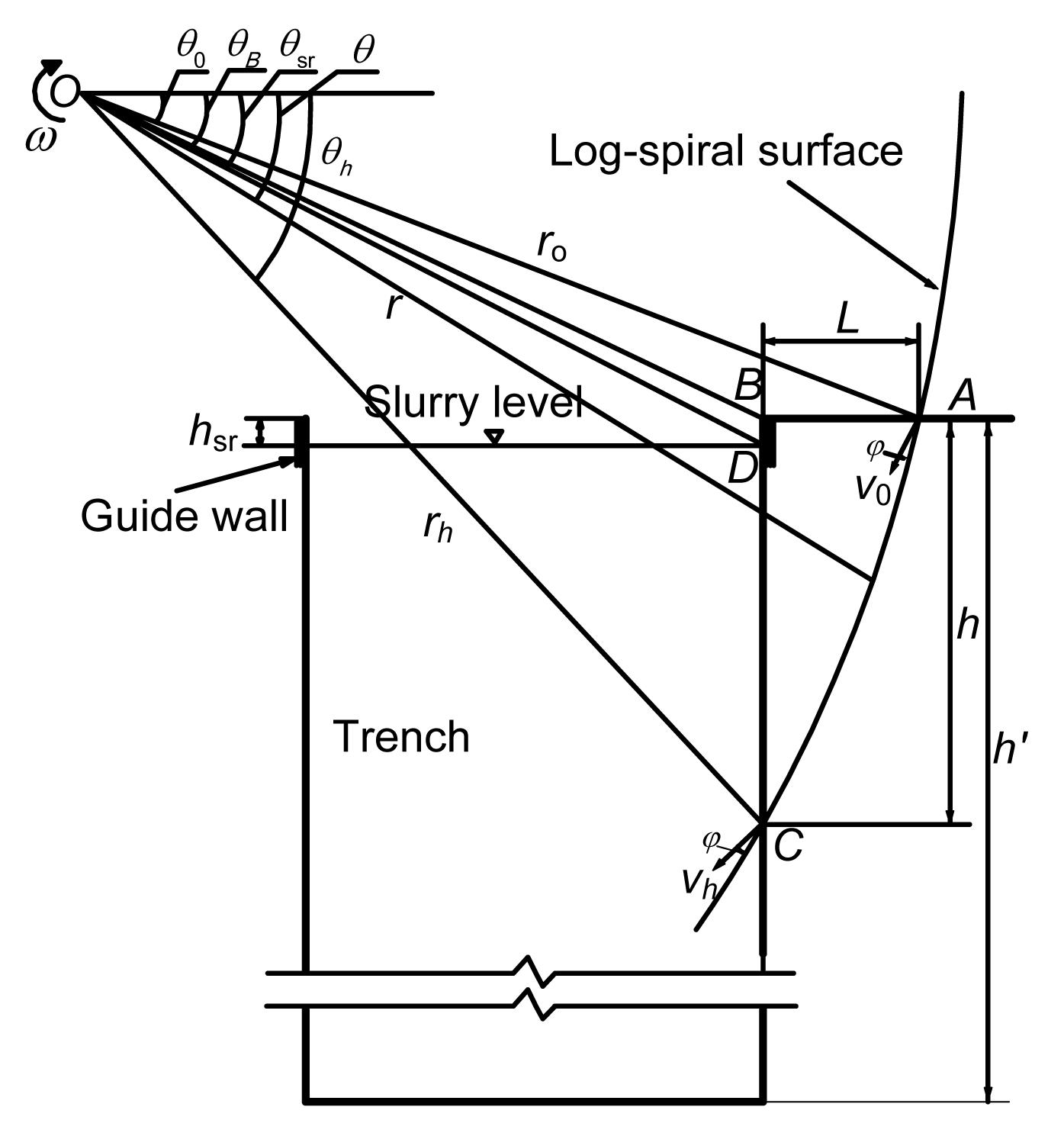
In this study, a 2D rotational mechanism with a log-spiral surface AC is shown in Fig. 1, in which the failure surface is assumed to pass through the toe of the slurry trench. The log-spiral slip surface is used for problems of slope stability (Chen et al., 2003; Loukidis et al., 2003; Zhu et al., 2003; Jiang et al., 2009) and foundation stability (Kumar and Ghosh, 2007; Han et al., 2012b). The region ABC rotates as a rigid body around the center of rotation O with the materials below the logarithmic surface AC remaining at rest. Thus, the surface AC is a surface of velocity discontinuity. In Fig.1, radii of r0, r and rh, angles of θ0, θB, θsr and θh, and distances of h and hsr are presented; ω is the angular velocity of the region ABC for rotation; and φ is the internal friction angle.
Fig.1 2D rotational mechanism for frictional/cohesive soil
Slurry trench can be considered as a special situation of the slope, when the slope angle is 90°. Expressions of the rate of internal energy dissipation (D) and the rate of work done by soil weight (Ws) for the 2D failure mechanism can be found in (Chen, 1975).
The work rate of the soil weight (Ws) can be written as
,
where γ is the unit weight of soil, ω is the angular velocity of the region ABC
for rotation, and r0 are shown in Fig. 1. The functions f1, f12 and f13 will be explained later in Eqs. (11)–(13).
The internal dissipation of energy occurs along the discontinuity surface AC. The total internal dissipation rate of energy (D) is found by integration over the whole surface. .
The slurry velocity (vsr) during rotation about axis O is ,
The slurry pressure is ,
where γsr is the unit weight of the slurry in the trench. The functions rx1, rx2 and h″ are defined by Eqs. (5)–(7). ,
,
.
The rate of external work (Wsr) due to the slurry pressure on CD is .
For a slurry trench of given geometry, it is possible to evaluate the safety factor, defined as .
The same expression of safety factor (F) for cohesive soil can be found in (Han et al., 2012a).
The safety factor (F) in Eq. (9) can then be obtained by substituting Eqs. (1), (2) and (8) into Eq. (9) as follows: .
In Eqs. (1) and (10), f11, f12, f13, f14, f15, θsr and θB are functions of soil strength parameters and geometry of the slip surface, which can be defined as follows: ,
,
,
,
,
,
,
where ,
,
where hsr is the distance from slurry level to trench top. The upper-bound theorem of limit analysis gives an upper bound for the value of the safety factor, F. The function F has a minimum value when θ0 and θh satisfy the conditions:
.
4. 3D analysis of slurry trench stability
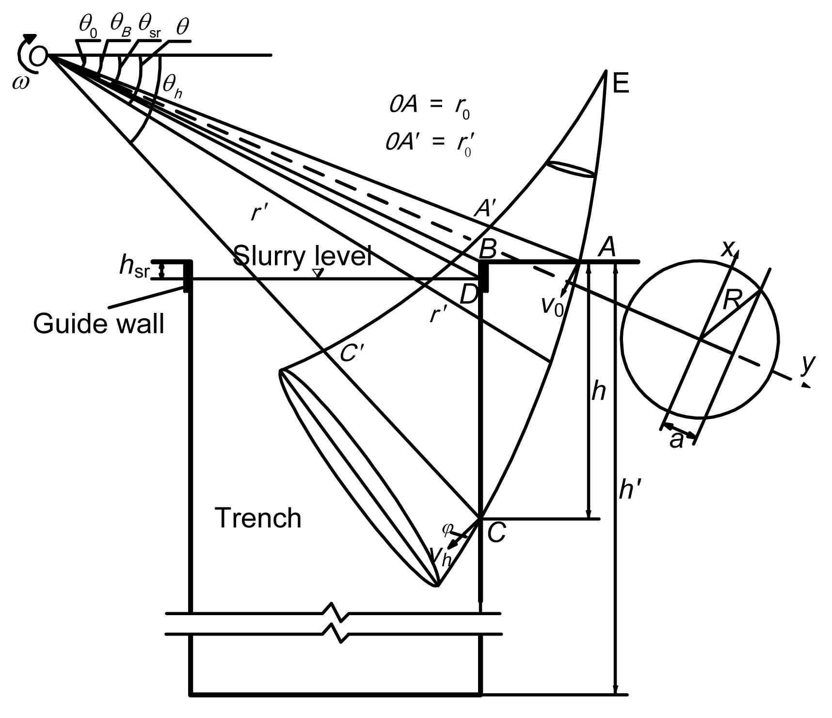
A 3D rotational mechanism is shown in Fig. 2 for frictional/cohesive soil with a logarithmic helicoid surface, in which the failure surface is assumed to pass through the top and the toe of the slurry trench. The same shape of this mechanism is considered by Michalowski and Drescher (2009), Han et al. (2013), and Xia et al. (2012) for the evaluating safety factor of slope. Soil over the failure surface rotates about the center of rotation O. Failure surface AC is the velocity discontinuous surface. Assume the mechanism can be specified completely by three variables. For convenience, we select the angles θ0, θh and .
Fig.2 3D rotational mechanism for frictional/cohesive soil
With the slope angle β=90°, expressions of the rate of internal energy dissipation (D) and the work rate of soil weight (Ws) for the 3D failure mechanism can be found in (Michalowski and Drescher, 2009; Han et al., 2013; Xia et al., 2012).
The work rate of the soil weight (Ws) can be written as .
The internal dissipation of energy (D) can be computed: .
where the functions rm, R, x1, x2, y1, a, d will be explained in Eqs. (27)–(29). The two integrals relate to the work rate in the upper portion of the slope, in the range (θ0, θB), and in the remaining part of the slope (θB, θh).
The slurry velocity during rotation about axis O is .
The slurry pressure is ,
where γsr is the unit weight of the slurry in the trench.
The rate of external work (Wsr) due to the slurry pressure is .
The safety factor in Eq. (9) can then be obtained by substituting Eqs. (21), (22), (25) into Eq. (9) as follows: .
In Eqs. (21), (22), (25) and (26), rm, R, x1, x2, y1, a, d, f21, f22, f23 and f24 are functions of soil strength parameters and geometry of the slip surface which can be defined as follows: ,
,
,
,
,
,
,
where
.
The function F has a minimum value when θ0, θh and
satisfy the conditions: .
5. Results and discussion
The estimates of safety factor F were obtained using a procedure for the given slurry and soil bulk density ratio, slurry level depth and trench depth ratio, cohesion, friction angle, trench width and depth ratio (in 3D), soil bulk density and trench depth. Independent variables in the procedure were: angles θ0 and θh, and ratio
(in 3D). These parameters were varied by a small increment in computational loops, and the process was repeated until the minimum of F was reached, with the increments of 0.1° used for angles θ0 and θh, and 0.01 for ratio .
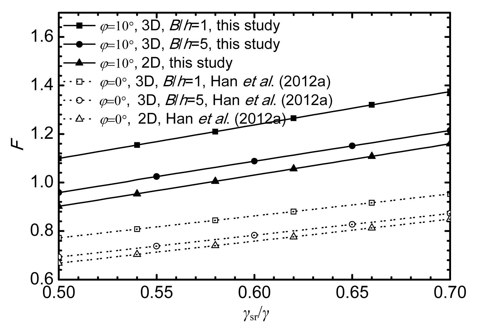
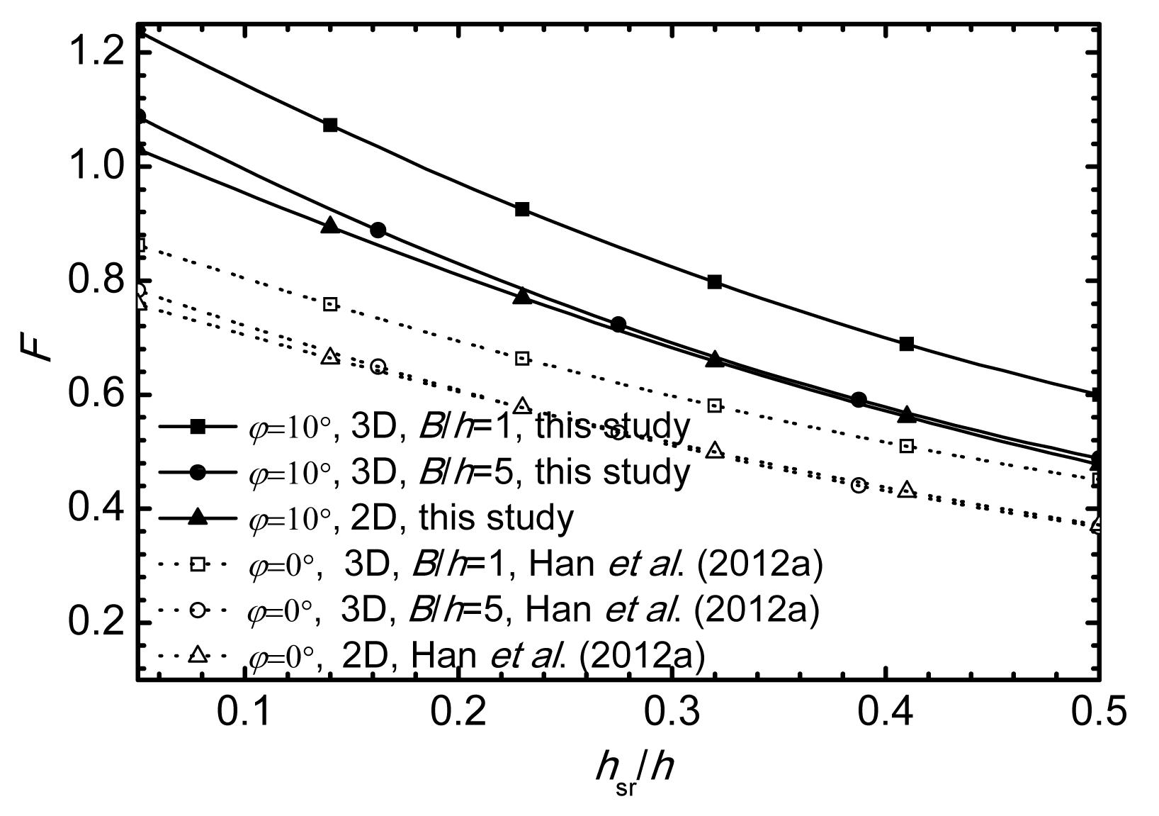
In this section, the solutions obtained by Han et al. (2012a) and Fox (2004) will be compared for various parameters, including γsr/γ, hsr/h, c, φ and B/h. The results of these computations are graphically represented in Figs. 3–7. The differences in 3D and 2D factors of safety of slurry trenches can be measured by the vertical distance between the respective lines in these figures. It can be found that the factors of safety increase with increasing slurry and soil bulk density ratio, cohesion, friction angle, and with decreasing slurry level depth and trench depth ratio, trench width and depth ratio.
Fig.3 Comparison of results with different γsr/γ for hsr/h=0.05, c=20 kPa, γ=18 kN/m3, and h=20 m
Fig.4 Comparison of results with different hsr/h for γsr/γ=0.6, c=20 kPa, γ=18 kN/m3, and h=20 m
Fig.5 Comparison of results with different c for γsr/γ=0.6, hsr/h=0.05, γ=18 kN/m3, and h=20 m
Fig.6 Comparison of results with different φ for c=20 kPa, γsr/γ=0.6, hsr/h=0.05, γ=18 kN/m3, and h=20 m
Fig.7 Variation of safety factor F with B/h for c=20 kPa, γsr/γ=0.6, hsr/h=0.05, γ=18 kN/m3, and h=20 m
In Figs. 3–5, and 7 the data points corresponding to φ=0° (cohesive soils), represent the solutions obtained by Han et al. (2012a). The analytical upper bound solutions of this study are higher than those presented by Han et al. (2012a). The friction angle φ>0° is the reason why the factors of safety obtained from this study are greater than those presented by Han et al. (2012a).
Figs. 6 and 7 also show the comparisons between the safety factor calculated from this study and from the limit equilibrium method by Fox (2004). It can be seen that the trends of the upper bound results are similar to those of Fox (2004), but the factors of safety obtained from this study are higher than those presented by Fox (2004). It means that, the factors of safety derived from the limit analysis method are higher than those calculated form the limit equilibrium method. The limit equilibrium analyses lead to a conservative estimate on the safety of slurry trenches. Using limit analysis can not only provide a useful way of analyzing the stability of slurry trenches, but can also avoid the shortcomings of the arbitrary assumptions of the limit equilibrium method (Yu et al., 1998).
6. Conclusions
The upper bound method for the 2D and 3D stability analysis of slurry trenches in frictional/cohesive soil are presented in this paper. It is investigated via examples for the effects of slurry and soil bulk density ratio, slurry level depth and trench depth ratio, cohesion, friction angle, trench width and depth ratio on slurry trench stability. The factor of safety increases with increasing slurry and soil bulk density ratio, cohesion, friction angle, and with decreasing slurry level depth and trench depth ratio, trench width and depth ratio. The factor of safety from a 3D analysis will approach the factor of safety from a 2D analysis gradually when the ratio of B/h increases. Using 2D solutions to evaluate the stability of 3D slurry trenches may underestimate factors of safety. Compared with the limit equilibrium method, the limit equilibrium method yields a conservative estimate on the safety factors.
[1] Chen, J., Yin, J.H., Lee, C.F., 2003. Upper bound limit analysis of slope stability using rigid finite elements and nonlinear programming. Canadian Geotechnical Journal, 40(4):742-752.
[2] Chen, W.F., 1975. Limit Analysis and Soil Plasticity. Elsevier Scientific Publication Co.,Amsterdam and New York :
[3] Drucker, D., Prager, W., Greenberg, H., 1952. Extended limit design theorems for continuous media. Quarterly of Applied Mathmatics, 9(4):381-389.
[4] Filz, G.M., Adams, T., Davidson, R.R., 2004. Stability of long trenches in sand supported by bentonite-water slurry. Journal of Geotechnical and Geoenvironmental Engineering, 130(9):915-921.
[5] Fox, P.J., 2004. Analytical solutions for stability of slurry trench. Journal of Geotechnical and Geoenvironmental Engineering, 130(7):749-758.
[6] Han, C.Y., Wang, J.H., Xia, X.H., Chen, J.J., 2012. Limit analysis for local and overall stability of slurry trench in cohesive soil. International Journal of Geomechanics, in press,:
[7] Han, C.Y., Xia, X.H., Wang, J.H., 2012. Upper bound solutions of ultimate bearing capacity of curved footing. Chinese Journal of Geotechnical Engineering, (in Chinese),34(2):230-236.
[8] Han, C.Y., Xia, X.H., Wang, J.H., 2013. Analytical Solutions for Three-Dimensional Stability of Coastal Slope. New Frontiers in Engineering Geology and the Environment, Springer Berlin Heidelberg,9:181-185.
[9] Hill, R., 1948. A variational principle of maximum plastic work in classical plasticity. The Quarterly Journal of Mechanics and Applied Mathematics, 1(1):18-28.
[10] Jiang, P.M., Sheng, H., Lu, C.F., Mei, G.X., 2009. Rigorous solution of the slope ultimate bearing capacity. Chinese Journal of Engineering Mechanics, (in Chinese),26(Suppl. 1):77-80.
[11] Kumar, J., Ghosh, P., 2007. Ultimate bearing capacity of two interfering rough strip footings. International Journal of Geomechanics, 7(1):53-62.
[12] Loukidis, D., Bandini, P., Salgado, R., 2003. Stability of seismically loaded slopes using limit analysis. Geotechnique, 53(5):463-479.
[14] Michalowski, R.L., Drescher, A., 2009. Three-dimensional stability of slopes and excavations. Geotechnique, 59(10):839-850.
[15] Ng, C., Lings, M., 1995. Effects of modeling soil nonlinearity and wall installation on back-analysis of deep excavation in stiff clay. Journal of Geotechnical Engineering, 121(10):687-695.
[16] Ng, C., Lings, M., Simpson, B., Nash, D., 1995. An approximate analysis of the three-dimensional effects of diaphragm wall installation. Geotechnique, 45(3):497-507.
[17] Ng, C.W.W., Yan, R.W.M., 1998. Stress transfer and deformation mechanisms around a diaphragm wall panel. Journal of Geotechnical and Geoenvironmental Engineering, 124(7):638-648.
[18] Ng, C.W.W., Yan, R.W.M., 1999. Three-dimensional modelling of a diaphragm wall construction sequence. Geotechnique, 49(6):825-834.
[19] Oblozinsky, P., Ugai, K., Katagiri, M., Saitoh, K., Ishii, T., Masuda, T., Kuwabara, K., 2001. A design method for slurry trench wall stability in sandy ground based on the elasto-plastic FEM. Computers and Geotechnics, 28(2):145-159.
[20] Tsai, J.S., 1997. Stability of weak sublayers in a slurry supported trench. Canadian Geotechnical Journal, 34(2):189-196.
[21] Tsai, J.S., Chang, J.C., 1996. Three-dimensional stability analysis for slurry-filled trench wall in cohesionless soil. Canadian Geotechnical Journal, 33(5):798-808.
[22] Tsai, J.S., Chang, C.C., Jou, L.D., 1998. Lateral extrusion analysis of sandwiched weak soil in slurry trench. Journal of Geotechnical and Geoenvironmental Engineering, 124(11):1082-1090.
[23] Tsai, J.S., Jou, L.D., Hsieh, H.S., 2000. A full-scale stability experiment on a diaphragm wall trench. Canadian Geotechnical Journal, 37(2):379-392.
[24] Xia, X.H., Han, C.Y., Wang, J.H., 2012. Analytical solutions for three-dimensional stability of limited slopes. Journal of Shanghai Jiaotong University (Science), 17(2):251-256.
[25] Xu, Y., Wei, Z., Zhou, G., Sun, Y., 2011. Analysis of stability of slurry trench sides of diaphragm wall based on construction parameters. Chinese Journal of Rock Mechanics and Engineering, (in Chinese),30(Suppl. 2):3464-3470.
[26] Yu, H.S., Salgado, R., Sloan, S.W., Kim, J.M., 1998. Limit analysis versus limit equilibrium for slope stability. Journal of Geotechnical and Geoenvironmental Engineering, 124(1):1-11.
[27] Zhu, D.Y., Lee, C.F., Jiang, H.D., 2003. Generalised framework of limit equilibrium methods for slope stability analysis. Geotechnique, 53(4):377-395.
Open peer comments: Debate/Discuss/Question/Opinion


Open peer comments: Debate/Discuss/Question/Opinion
<1>