Affiliation(s):
1.
School of Civil Engineering, Harbin Institute of Technology, Harbin 150090, China; moreAffiliation(s): 1.
School of Civil Engineering, Harbin Institute of Technology, Harbin 150090, China; 2.
Key Lab of Structures Dynamic Behavior and Control (Harbin Institute of Technology), Ministry of Education, Harbin 150090, China; less
Chang-yu Cui, Bao-shi Jiang, You-bao Wang. Node shift method for stiffness-based optimization of single-layer reticulated shells[J]. Journal of Zhejiang University Science A, 2014, 15(2): 97-107.
@article{title="Node shift method for stiffness-based optimization of single-layer reticulated shells", author="Chang-yu Cui, Bao-shi Jiang, You-bao Wang", journal="Journal of Zhejiang University Science A", volume="15", number="2", pages="97-107", year="2014", publisher="Zhejiang University Press & Springer", doi="10.1631/jzus.A1300239" }
%0 Journal Article %T Node shift method for stiffness-based optimization of single-layer reticulated shells %A Chang-yu Cui %A Bao-shi Jiang %A You-bao Wang %J Journal of Zhejiang University SCIENCE A %V 15 %N 2 %P 97-107 %@ 1673-565X %D 2014 %I Zhejiang University Press & Springer %DOI 10.1631/jzus.A1300239
TY - JOUR T1 - Node shift method for stiffness-based optimization of single-layer reticulated shells A1 - Chang-yu Cui A1 - Bao-shi Jiang A1 - You-bao Wang J0 - Journal of Zhejiang University Science A VL - 15 IS - 2 SP - 97 EP - 107 %@ 1673-565X Y1 - 2014 PB - Zhejiang University Press & Springer ER - DOI - 10.1631/jzus.A1300239
Abstract: This paper presents a node shift method to find the optimal distribution of nodes in single-layer reticulated shells. The optimization process searches for the minimum strain energy configuration and this leads to reduced sensitivity in initial imperfections. strain energy sensitivity numbers are derived for free shift and restricted shift where nodes can move freely in the 3D space or have to move within a predefined surface respectively. Numerical examples demonstrate the efficiency of the proposed approach. It was found that optimized structures achieve higher ultimate load and are less sensitive to imperfections than the initial structure. The configuration of the final structure is closely related to factors like the initial structural configuration, spatial conditions, etc. Based on different initial conditions, architects can be provided with diverse reasonable structures. Furthermore, by amending the defined shapes and nodal distributions, it is possible to improve the mechanical behavior of the structures.
Darkslateblue:Affiliate; Royal Blue:Author; Turquoise:Article
Article Content
1. Introduction
Single-layer reticulated shells are widely utilized in civil engineering. Their shapes either are free form surfaces defined via computer graphics technology or predefined surfaces like, for example, Kiewitte single layer domes, cylindrical shells, and saddle shells. However, the process of shape construction does not correspond to optimizing the mechanical behavior of the structure. Furthermore, nodal distribution of the grid is artificially divided. There is a tremendous amount of literature on the optimization of trusses and frames, including topology, shape and sizing optimization. The most popular method is genetic algorithm and its variants (Balling et al., 2006; Rahami et al., 2008; Chan and Wong, 2008). The node shift technique is a well established approach to shape/layout optimization of trusses, although it was proposed for weight minimization (Wang et al., 2002a; 2002b). Other methods include simulated annealing (Hasancebi and Erbatur, 2002; Lamberti, 2008), particle swarm optimization (Perez and Behdinan, 2007; Zhong et al., 2008), ant colony optimization (Kaveh et al., 2008), and the growing ground structure method (Hagishita and Ohsaki, 2009). However, these methods were seldom applied to single-layer reticulated shells. Some studies aimed to reduce structural weight of reticulated shells with sizing optimization (Mu et al., 2006; Liu et al., 2007). However, mechanical behavior (for example, sensitivity to initial imperfections) resulting from the node layout was not optimized (Shen and Chen, 1999; Mu et al., 2006).
Nodal layout in the structural grid and structural shape are the most important factors governing the overall mechanical behavior of the reticulated structure, and there is little space to change shell topology by rod additions or eliminations. For this reason, a layout optimization method based on node shift is developed to improve mechanical behavior of single-layer reticulated shells. Nodal coordinates are adjusted to achieve reasonable structural morphology featuring minimum strain energy, which is obtained by evaluating the sensitivity of strain energy to nodal positions. The proposed approach generalizes the height adjusting method (Cui and Yan, 2006) which also was based on the idea of minimizing structural strain energy via node shifting. While the height adjusting method just shifts nodes in the vertical direction (z-coordinate), in the present method nodes can either move freely in 3D space or amend their positions on a predefined surface. In this way, it is possible to assess the influence of the node layout and rod lengths on the overall mechanical behavior of the structure as well as to meet architectural requirements. The proposed method leads to reduced sensitivity to imperfections as the sensitivity of strain energy with respect to variations of nodal position reaches zero in the convergence process.
This paper is organized as follows. First, two strain energy sensitivity numbers for free shift and restricted shift on a predefined surface are derived. Second, a simple structure is studied to demonstrate the features of the proposed method. Finally, typical structures are optimized to illustrate various applications of the method, such as shape amendment, nodal distribution amendment and generation of a free form surface.
2. Determination of nodal shift strain energy sensitivity
2.1. Feature of the strain energy sensitivity
Design optimization for the maximum stiffness can be stated as follows:
where C(P) is the strain energy that depends on nodal coordinate vector P=[P1, P2, …, Pn]T, S is the curved surface shape of reticulated shells; Ω0 is the design space, whose geometry can be described by analytic functions or B-splines and surface equations; δmax and σmax are the maximum stress and maximum displacement, respectively, with the corresponding limits δ0 and σ0. In this study, δ0 and σ0 were set as L/400 (L is the span of a latticed structure) and 210 MPa, respectively. In general, cross-sections of rods are selected according to the design experience, while δ0 and σ0 are set based on design specifications. Since the proposed method maximizes structural stiffness thus reducing the maximum displacement and bending moment, constraints on the maximum displacement and stress are often inactive. Therefore, the optimization problem Eq. (1) actually is an unconstrained problem where the optimizer converges to a design satisfying stress and displacement constraints. Conversely, the cross-sectional areas of rods should be increased properly.
Weight constraints also should be considered in practical engineering applications. However, weight budget is usually specified by the designer. In the present case, artificial weight restriction was avoided as much as possible.
The Taylor expansion of the strain energy in the neighborhood of a design point Ps is
If ΔP is small enough, only the first order item can be retained and Eq. (2) becomes:
.
The sensitivity of strain energy αs to nodal coordinates Ps is expressed as
.
Eq. (3) shows that if the sensitivity approaches to zero, strain energy does not change significantly and mechanical response of the structure becomes insensitive to changes in nodal coordinates. The strain energy sensitivity approach, not yet considered in literature, may be very effective in the optimization of single-layer reticulated shells. In particular, optimization may reduce sensitivity to geometric imperfections.
Since negative strain energy sensitivity corresponds to moving along the steepest descent direction, the topology/shape of the structure yielding a reduction of strain energy can be found. By iterating this process, strain energy is minimized. At convergence, strain energy becomes insensitive to any change in nodal coordinates.
Strain energy sensitivities are now derived for free and restricted node shifts, and the derivation is done in the linear-elastic range.
2.2. Determination of strain energy sensitivity for free node shift
If the coordinates x, y, and z of the jth node are independent, strain energy can be expressed as the work done by external forces:
,
where F is the vector of applied loads, and U is the vector of nodal displacements.
The equilibrium equation for a skeletal structure can be written as
,
where K is the global stiffness matrix. The force vector F is usually supposed not to vary during the design process. Basically, loads are independent of design variables. Therefore, differentiating both sides of Eqs. (5) and (6) with respect to the nodal coordinate xj, one obtains:
,
.
By combining Eqs. (7) and (8), the sensitivity of strain energy with respect to the nodal coordinate xj can be expressed as
.
Sensitivity can be evaluated for each nodal coordinate x, y or z.
Since differentiation of the global stiffness matrix depends only on the stiffness of the elements including the jth node, it can be written as
,
where the vector U(ij) includes the nodes of the elements that share the jth node, and is the sum of the stiffness matrices of elements sharing the jth node.
2.3. Determination of strain energy sensitivity for restricted node shift
Assuming that coordinates xj and yj of the jth node are independent while coordinate zj is a function of xj and yj. The z-coordinate is calculated from the surface equation z=f(x, y) when nodal coordinates xj and yj are perturbed.
By utilizing a derivation similar to that for Eqs. (5) and (6), the sensitivity of strain energy with respect to the nodal coordinate xj can be obtained:
.
The differentiation of global stiffness matrix is expressed as
.
According to matrix product rules, the strain energy sensitivity is
,
where α′xj and α′zj are the strain energy sensitivity terms corresponding to the case of independent nodal coordinates x, y, and z. Similarly, y can be used in place of x if the sensitivity with respect to the y-coordinate is to be determined. Eq. (13) allows the numerical implementation of the proposed node-shift method to be greatly simplified.
3. Optimization process
To reduce strain energy, nodal coordinates must be perturbed in the direction opposite to the strain energy sensitivity vector α, i.e.,
.
Therefore, Eq. (3) can be rewritten as
.
Strain energy decreases if a positive parameter λ is properly set, which is expressed as
.
To optimize the structure surface, node positions are gradually adjusted as follows:
.
In the present case, λ changed adaptively in the optimization process and its value was determined by the Golden section method.
The optimization process can be summarized as follows:
Choose the initial shape of the structure according to architectural, visual, and structural considerations;
Compute sensitivities of nodal strain energy via finite element analysis;
Repeat steps 2 and 3 until convergence. The convergence criterion may be:
.
By changing the distribution of nodes, it is possible to optimize the structure. If nodes become so close that they merge into one, the corresponding rods are eliminated (i.e., topology optimization). However, for all the test problems solved in this study, the number of nodes remained constant. At present, most of the literature for optimization methods on the single-layer reticulated shells is the size optimization methods for the structural weight minimum, for example, Liu et al. (2007) and Mu et al. (2006), and there is little literature on shape/topology optimization. Therefore, for the comparison in the future, this study provided the data of the first test problem (in Section 4.1). The optimization algorithm was coded in Fortran language and the beam element was selected to model the structures. The optimization runs and nonlinear analyses entailed by this study were carried out on a standard PC equipped with an Intel 2.83 GHz Quad-core CPU and 3 GB of RAM memory.
4. Test problems and optimization results
4.1. Features of the proposed method
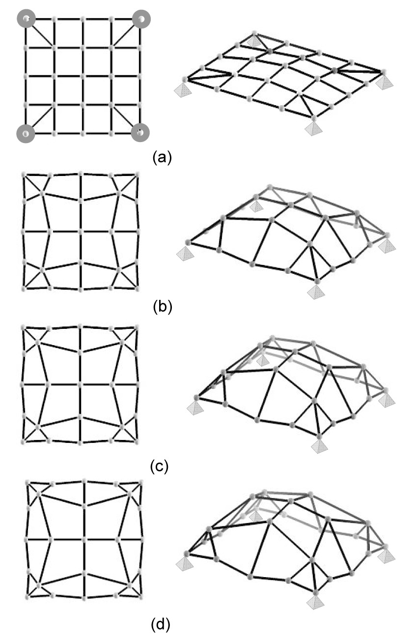
The first test problem demonstrates the validity of the proposed approach. For this purpose, a 4 m×4 m centrosymmetric square-section surface supported at the four corners by hinges (Fig. 1a) was considered: the initial shape of the structure is slightly convex with 25 nodes. All free nodes are subjected to 10 N vertical loads. The cross-sectional area of the rods is 2.73 cm2, the bending and torsion moments of the inertia of the section are 2.9 cm4 and 5.8 cm4, respectively. The elastic modulus of the material is 210 GPa, Poisson’s ratio is 0.3, and yield strength is 335 MPa. The allowable displacement is 1 cm. The structures were fully modeled without simplification.
Fig.1 Shape variation of the 4 m×4 m square surface structure occurring in the optimization process (a) Step 1; (b) Step 20; (c) Step 45; (d) Step 65
The intermediate shapes obtained in the optimization process are shown in Fig. 1. The central nodes gradually rise up from the initially slightly convex configuration while intermediate nodes located on the boundaries go below the initial surface; the nodes close to the supports approach the location of kinematic constraints. The final shape of the optimized structure is consistent with applied loads. The optimization process lasted 67 iterations for a computation time of 18.4 s.
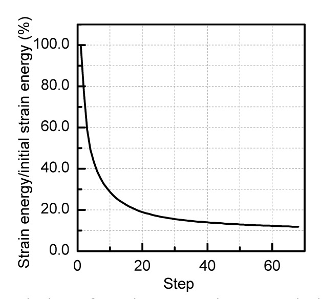
Fig. 2 shows the change of strain energy throughout the optimization process. After a fast reduction in early optimization cycles, strain energy gradually converged after Step 15. Various shapes can be obtained in the region of the smooth variation of strain energy. The strain energy of the optimized structure (Step 65) decreased by about 87% with respect to the initial design while the structural weight increased by about 11.3%. This demonstrated that structural behavior improves by a great deal in spite of a slight increase in weight. Table 1 shows the changes of nodal coordinates from the initial design to the optimized structure.
Fig.2 Variation of strain energy in the optimization process of the 4 m×4 m square surface structure
Table 1
Variation of nodal coordinates in test problem 1
Node number
Initial structure (x, y, z)
Optimized structure (Step 65) (x, y, z)
1
(0.0, 0.0, 0.0)
(0.0, 0.0, 0.0)
2
(1.0, 0.0, 0.0)
(0.885, 0.053, 0.079)
3
(2.0, 0.0, 0.0)
(2.000, −0.041, −0.094)
4
(3.0, 0.0,0.0)
(3.115, 0.053, 0.079)
5
(4.0,0.0, 0.0)
(4.0, 0.0, 0.0)
6
(0.0, 1.0, 0.0)
(0.053, 0.885, 0.079)
7
(1.0, 1.0, 0.1)
(0.402, 0.402, 0.716)
8
(2.0, 1.0, 0.2)
(2.0, 0.831, 1.256)
9
(3.0, 1.0, 0.1)
(3.598, 0.402, 0.716)
10
(4.0, 1.0, 0.0)
(3.947, 0.885, 0.079)
11
(0.0, 2.0, 0.0)
(−0.041, 2.0, −0.094)
12
(1.0, 2.0, 0.2)
(0.831, 2.0, 1.256)
13
(2.0, 2.0, 0.3)
(2.0, 2.0, 1.461)
14
(3.0, 2.0, 0.2)
(3.169, 2.0, 1.256)
15
(4.0, 2.0, 0.0)
(4.041, 2.0, −0.094)
16
(0.0, 3.0, 0.0)
(0.053, 3.115, 0.079)
17
(1.0, 3.0, 0.1)
(0.402, 3.598, 0.716)
18
(2.0, 3.0, 0.2)
(2.0, 3.169, 1.256)
19
(3.0, 3.0, 0.1)
(3.598, 3.598, 0.716)
20
(4.0, 3.0, 0.0)
(3.947, 3.115, 0.079)
21
(0.0, 4.0, 0.0)
(0.0, 4.0, 0.0)
22
(1.0, 4.0, 0.0)
(0.885, 3.946, 0.079)
23
(2.0, 4.0, 0.0)
(2.0, 4.041, −0.094)
24
(3.0, 4.0, 0.0)
(3.115, 3.947, 0.079)
25
(4.0, 4.0, 0.0)
(4.0, 4.0, 0.0)
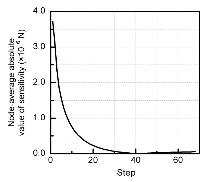
Fig. 3 shows that the trend of the variation of the average absolute value of nodal strain energy sensitivity is similar to that exhibited by the strain energy and finally tends to zero. Furthermore, the maximum bending moment and maximum axial force developed in the optimized structure are respectively 6.4% and 60.2% of their counterpart evaluated for the initial design. The maximum displacement and the maximum stress are 3.9×10⁻⁴ cm and 8.4×10⁻³ MPa, respectively. Therefore, the optimized structure can satisfy the constraints of maximum stress and displacement.
Fig.3 Variation of average absolute value of nodal strain energy sensitivity in the optimization process of the 4 m× 4 m square surface structure
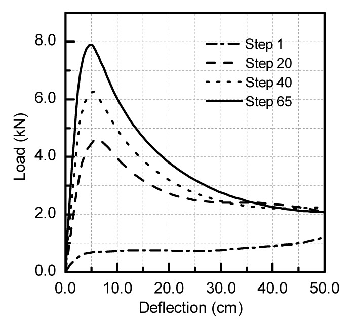
The increase in stiffness resulting from the proposed nodal shift method leads to improved static stability and makes the structure less sensitive to initial imperfections. For example, Fig. 4 shows the load-deflection curves of the perfect structure evaluated for the initial design (i.e., Step 1) and intermediate designs corresponding to the 20th, 40th, and 65th iterations (the “load” in “load-deflection” means that the same nodal loads were applied to every node). For the intermediate design found in Step 65, the nonlinear collapse analysis was carried out including different initial geometric imperfections of amplitude 0 (i.e., perfect structure), L/1000, L/500, L/300, L/200, and L/100, respectively. The sign of the imperfection was consistent with the first buckling mode, which was most unfavorable for the stability of reticulated shells (this approach is known as the consistent imperfection mode method, please refer to Shen and Chen (1999) and Fan et al. (2010)). For this purpose, a finite element model including material and geometric nonlinearity was developed in ANSYS, modeling rods as Timoshenko’s beam elements. Nonlinear analysis was carried out after the optimized process which did not include any constraint on the minimum collapse load. As strain energy decreases, ultimate load and tangent stiffness increase until nonlinear collapse (Fig. 4). It can be seen from Fig. 5 that the optimized structure becomes less sensitive to initial geometric imperfections. In fact, the ultimate loads corresponding to L/1000, L/500, L/300, L/200 and L/100 imperfection amplitudes do not change significantly and are respectively 99.5%, 99.1%, 98.9%, 97.6%, and 97.5% the ultimate load of the perfect structure. Incidentally, the optimization problem on the collapse load can also be solved by the sensitivity of first-order eigenvalue about the nodal coordinates; unfortunately, the second and the third order eigenvalues, etc., might decline, and be lower than the first-order eigenvalue. This needs further study.
Fig.4 Variation of load-deflection curve of the perfect structure occurring in the optimization process of the 4 m×4 m square surface structure
Fig.5 Imperfection sensitivity evaluated for the optimized design of the 4 m×4 m square surface structure in Step 65
This test problem disclosed two possible engineering applications of the proposed method: (1) to immediately improve the mechanical behavior of an existing structure as strain energy drops quickly in the initial stages of the optimization process; (2) to create free and flexible curved surfaces by adjusting nodal coordinates through the evaluation of strain energy sensitivities that may be positive, negative or zero.
Practical optimization problems are solved in the following sections to prove the suitability of the proposed approach for shape amendment, nodal distribution amendment of single-layer reticulated shells, and morphogenesis of free form surface shells.
4.2. Shape amendment of conventional surfaces
The objective of the second test problem is to amend the shape of the K6 reticulated shell with 61 nodes as shown in Fig. 6a. Nodal coordinates x, y, and z are adjusted by means of the free node shift method. The span L of the dome is 30 m and its height is 9.8 m. The cross-sectional area of elements is 10.21 cm2 with a bending moment of inertia of 54.24 cm4, and a torsional moment of inertia of 108.49 cm4. The elastic modulus of the material is 210 GPa, and Poisson’s ratio is 0.3. The structure is subject to a uniformly distributed vertical load of 2.5 kN/m2 and is pin-supported at the boundary nodes.
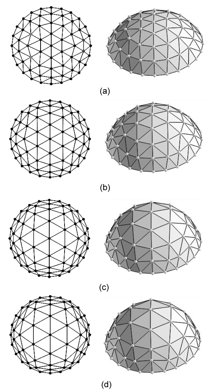
Fig.6 Shape variation of the K6 reticulated shell structure occurring in the optimization process (a) Step 1; (b) Step 15; (c) Step 75; (d) Step 130
Fig. 6 shows the variation of shape in the optimization process: since the nodes of the center zone of the reticulated shell moved outward and upward, the shell surface rose up and turned from a spherical to a paraboloid shape. The grid of nodes in the central portion became sparse while the grid near the supports became dense. Redistribution of nodes enhanced structural stiffness near the supports. Rods finally formed cross-arches thus achieving the expected structural shape. Finally, the height of the optimized shell (Step 130) increased to about 19.88 m.
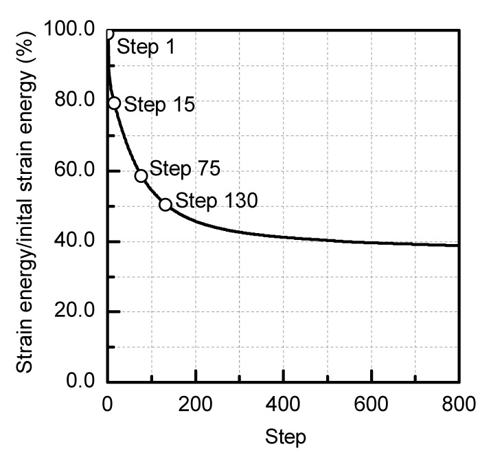
The variation of strain energy in the optimization process is presented in Fig. 7. While the structural shape changed slowly, the strain energy decreased rapidly in the early iterations. In order to prevent unwanted changes from the target K6 structural shape, the intermediate design obtained in Step 130 was taken as the final optimized structure. Strain energy in Steps 15, 75, and 130 dropped to about 20.1%, 40.2%, and 50.1% of the energy possessed by the initial structure, respectively. This proves that the amending structural shape can significantly increase the stiffness of the structure without changing the original architectural intention.
Fig.7 Variation of strain energy in the optimization process of the K6 reticulated shell structure
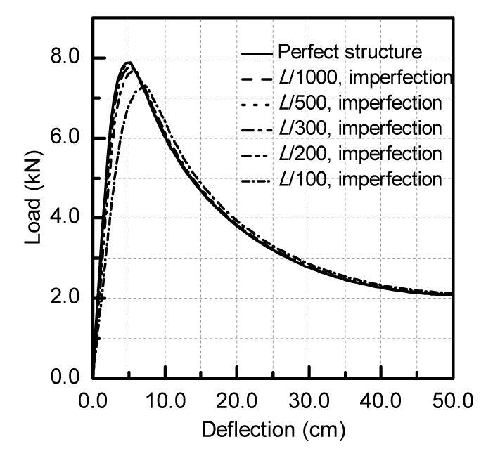
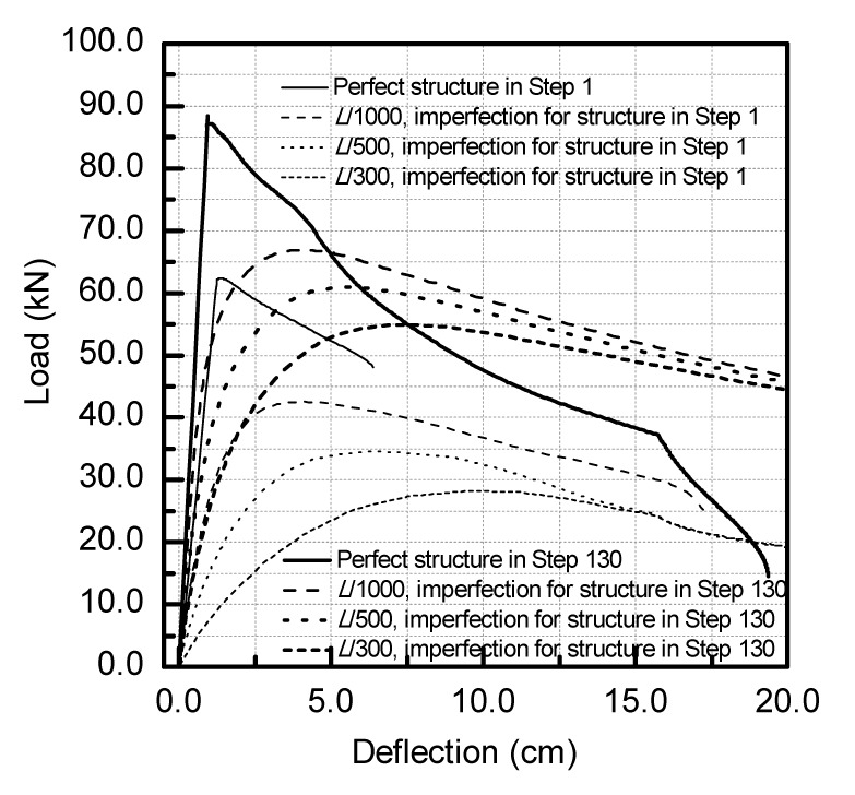
Fig. 8 shows the variation of the load-deflection curve in the optimization process. The ultimate load increased gradually from 62.3 kN to 87.2 kN. Load paths gradually became steeper which indicated that the structural tangent stiffness was gradually improved. Fig. 9 compares the load-deflection curves for different amplitudes of geometrical imperfection (respectively, L/1000, L/500, and L/300) evaluated for the initial design and the optimized design corresponding to Step 130. In the case of the initial design, the ultimate load dropped down to 45.3% of the ultimate load of the perfect structure. Conversely, in the case of the optimized design, the ultimate load was still 64.1% of the perfect structure. This confirms that the proposed approach can significantly improve the mechanical behavior of the structure by simultaneously increasing stiffness and ultimate load and reducing sensitivity to geometric imperfections.
Fig.8 Variation of load-deflection curve of the perfect structure occurring in the optimization process of the K6 reticulated shell structure
Fig.9 Imperfection sensitivity of the K6 reticulated shell structure
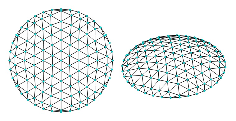
The third test problem is concerned with the adjustment of the z-coordinates of the surface nodes. The K6 reticulated dome with 127 nodes shown in Fig. 10a (50 m span and 8.3 m high) was taken as the initial structure. The cross-sectional area of the rods is 27.49 cm2 with bending and torsion moments of inertia of 1053.17 cm4 (Ix=Iy) and 2106.34 cm4, respectively. The elastic modulus of the material is 210 GPa, and Poisson’s ratio is 0.3. The structure is subject to a uniformly distributed vertical load of 10 kN/m2 and is pin-supported at the boundary nodes.
Fig.10 Schematic of K6 single-layer reticulated shell (a) and optimized shape of K6 reticulated shell obtained by shifting only the z-coordinates of nodes (b)
The optimized configuration shown in Fig. 10b corresponds to the 50th iteration: the structure evolved into a paraboloid reticulated shell. The strain energy evaluated for the optimized design is about 35.4% of its counterpart for the initial structure. The height of the optimized shell increased to about 19.3 m while the horizontal projection of the structural grid remained the same. Changes in mechanical behavior were similar to the previous test case and are hence omitted for brevity.
In summary, by changing all coordinates or only z-coordinates, it is possible to determine the shape of the structure that best fits the architectural concepts.
4.3. Amendment of nodal distribution of reticulated shells
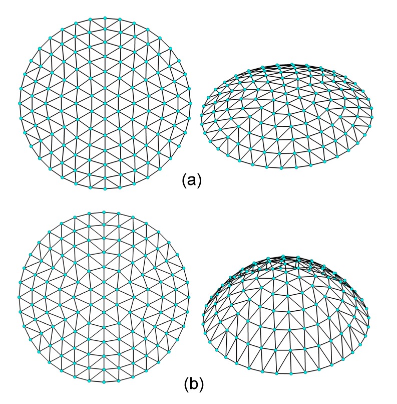
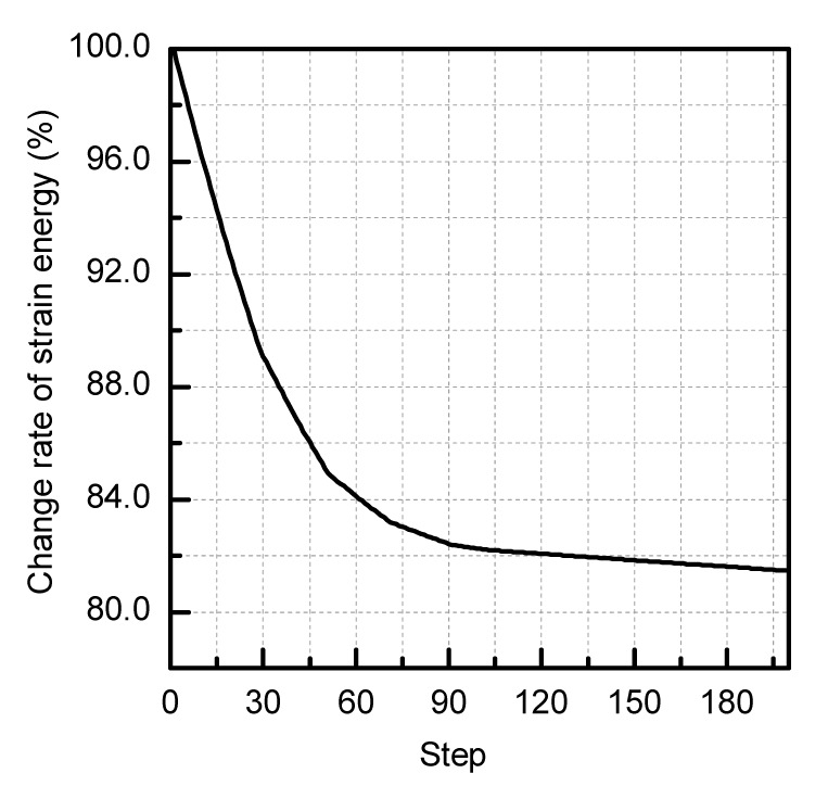
The next two test problems considered the case of a restricted node shift. The first example took the same initial design and material properties of the K6 reticulated shell schematized in Fig. 6. The shape determined in the 150th iteration was set as the optimized design (Fig. 11): the strain energy was 81.8% of the strain energy corresponding to the initial design (Fig. 12). As expected, redistribution of the structural nodes has led to disposing of the structural rods so as to form cross-arches.
Fig.11 Optimized shape of the first K6 reticulated shell obtained by restricting nodal shifts
Fig.12 Variation of strain energy in the optimization process of the K6 reticulated shell structure with restricted nodal shifts
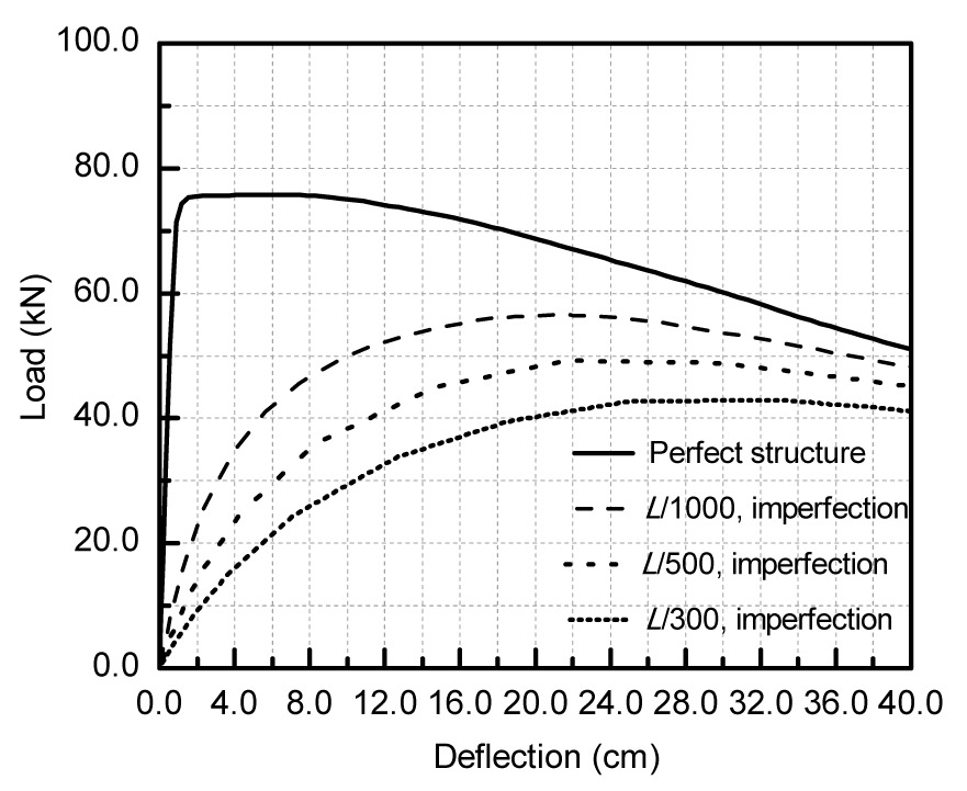
The collapse load of the optimized structure was higher than that of the initial configuration: 75.8 kN vs. 62.3 kN. Load-deflection curves of the optimized structure evaluated by different initial imperfections are shown in Fig. 13. The smallest ultimate load is 55.63% of that of the perfect shell, and the optimized structure is also less sensitive to imperfections than the initial configuration (similar to what is shown in Fig. 9). The optimization results indicate that static stability of single layer reticulated shells can be enhanced also by using the restricted node shift method although the improvement in static stability and insensitivity to imperfections are less pronounced than that in the case of free node shifting. This is due to the smaller amount of design freedom included in the optimization process with respect to the case of free 3D movements of nodes.
Fig.13 Imperfection sensitivity of the K6 reticulated shell structure optimized with restricted nodal shifts
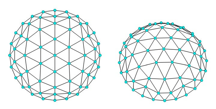
The second example of the nodal distribution amendment took the same initial design and material properties of the K6 reticulated shell (Fig. 10a). The shape determined in the 100th iteration was set as the optimized design (Fig. 14), where the strain energy is 86.5% of that evaluated for the initial design. The optimized structure again formed cross-arches. Changes in the mechanical behavior resulting from the optimization process are not discussed in detail for brevity.
Fig.14 Optimized shape of the second K6 reticulated shell obtained by restricting nodal shifts
4.4. Generation of free-form surface reticulated shells
In practical engineering, especially at early design stages, structural shapes must satisfy mechanical requirements as well as architectural considerations. In view of this, the following procedure can be adopted in structural engineering design: (1) integrate architectural, structural, equipment and environmental working conditions and concepts, set design space and design constraints, model the initial structure; (2) optimize the shape of the initial structure with the node shift method; (3) evaluate the structural shape obtained from the optimization: if the shape meets the architectural requirements, refine design through local amendments of shapes, otherwise adjust design variables and repeat Steps 2 and 3.
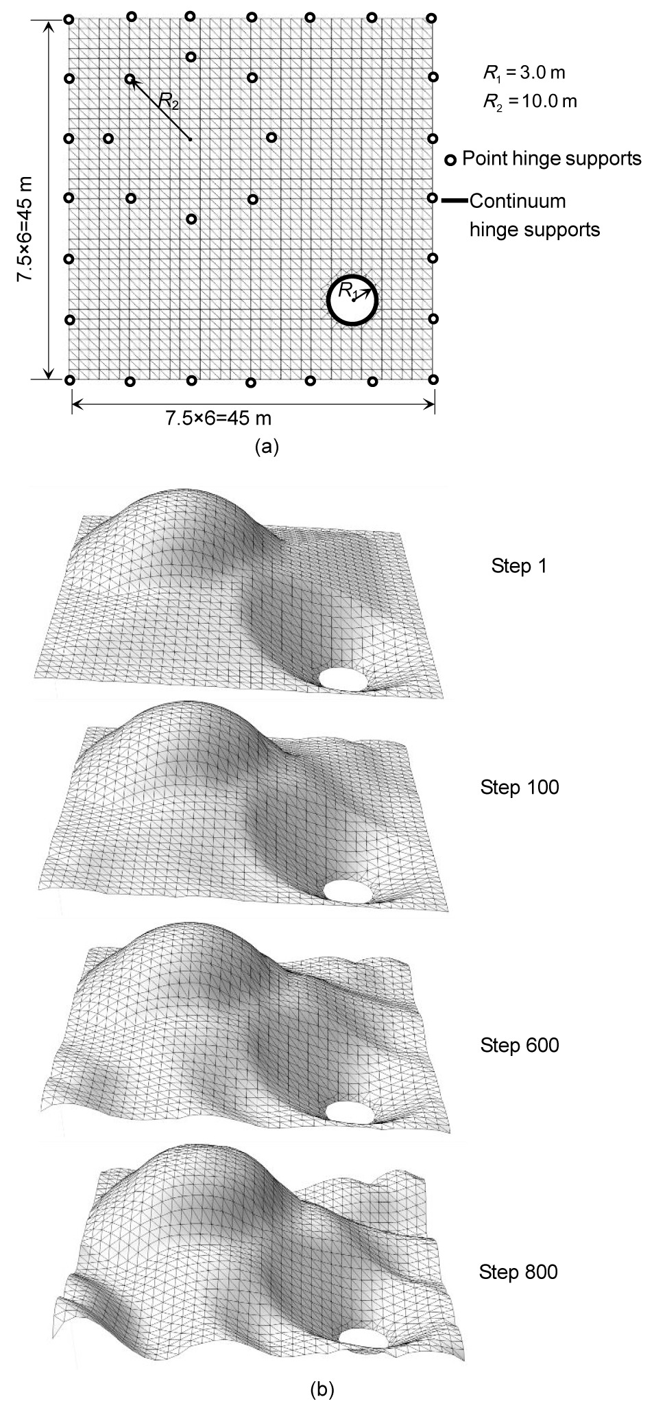
For example, Fig. 15a shows the map drawing of a theater building, according to architectural requirements, a 45 m×45 m area. The initial shape with 1384 nodes is dictated by the architectural functions, visual requirements, and comprehensive analysis of the possible final shape. The structure, subject to a 2.5 kN/m2 distributed load, is comprised of Φ70 m×5 m steel tubes. The elastic modulus of the material is 210 GPa, and Poisson’s ratio is 0.3. The displacement limit is 4 cm.
Fig.15 Optimization process of the theater building (a) Layout view of the theater building; (b) Variation of shape in the free-curved surface optimization process
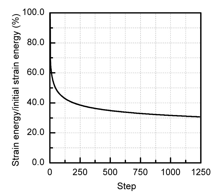
Only the nodal z-coordinate was adjusted in the optimization process (Fig. 15b). Flat regions initially became softly curved concave and convex areas whose curvature increased with optimization iterations. A reticulated shell of free-form curved surfaces with distinct tension and compression areas was gradually formed. Fig. 16 shows the monotonic reduction of strain energy in the optimization process: at convergence, strain energy was about 30% of that of the initial structure.
Fig.16 Variation of strain energy in the optimization process of the theater building
The optimized design satisfied structural requirements: the average vertical and horizontal displacements are 0.8 and 0.15 cm, respectively, and the corresponding largest displacements are 3.24 and 0.98 cm, which are smaller than the 4 cm allowable displacement. It can be seen from Fig. 15b that the height of the curved surface may increase or decrease in the successive design cycles. The structural shape evolves towards a free-form surface thus achieving a good visual effect in comparison with traditional reticulated shells.
5. Conclusions
This paper presented a node shift sensitivity method to optimize single-layer reticulated shells. By minimizing strain energy it is possible to increase collapse load and reduce sensitivity to geometric imperfections. The optimization results obtained in the test problems solved in this study demonstrate with no shadow of a doubt that the proposed approach is suitable for modifying the shape and nodal distribution of existing single-layer reticulated shells in order to improve their mechanical behavior as well as to generate the free-form surface reticulated shells according to architectural considerations.
Pre-existing structures designed on the basis of architectural considerations may be improved in terms of mechanical behavior by performing a few design cycles since the proposed method allows strain energy to be rapidly reduced in the initial phase of the optimization process. In this way, it is possible to obtain a variety of reasonable free-from shape surfaces given different initial shapes and/or spatial conditions. This is of paramount importance in the determination of the best structural shape in the design stage of the architectural scheme.
[1] Balling, R.J., Briggs, R.R., Gillman, K., 2006. Multiple optimum size/shape/topology designs for skeletal structures using a genetic algorithm. Journal of Structural Engineering, 132(7):1158-1165.
[2] Chan, C.M., Wong, K.M., 2008. Structural topology and element sizing design optimization of tall steel frameworks using a hybrid OC-GA method. Structural and Multidisciplinary Optimization, 35(5):473-488.
[3] Cui, C.Y., Yan, H., 2006. A morphosis technique for curved-surface structures of arbitrary geometries—height adjusting method and its engineering applications. China Civil Engineering Journal, (in Chinese),39(12):1-6.
[5] Hagishita, T., Ohsaki, M., 2009. Topology optimization of trusses by growing ground structure method. Structural and Multidisciplinary Optimization, 37(4):377-393.
[6] Hasancebi, O., Erbatur, F., 2002. Layout optimisation of trusses using simulated annealing. Advances in Engineering Software, 33(7-10):681-696.
[7] Kaveh, A., Hassani, B., Shojaee, S., Tavakkoli, S.M., 2008. Structural topology optimization using ant colony methodology. Engineering Structures, 30(9):2559-2565.
[8] Lamberti, L., 2008. An efficient simulated annealing algorithm for design optimization of truss structures. Computers & Structures, 86(19-20):1936-1953.
[9] Liu, Z.F., Yan, Z.T., Wang, Y.S., Li, Z.L., 2007. Scheme selection and optimum design of single-layer reticulated domes. Journal of Chongqing Jianzhu University, (in Chinese),29(4):83-86.
[10] Mu, Z.G., Liang, J., Sui, J., Ning, P.H., Yan, M., 2006. Study of optimum design of single layer dome structures based on niche genetic algorithm. Journal of Building Structure, (in Chinese),27(2):115-119.
[11] Perez, R.E., Behdinan, K., 2007. Particle swarm approach for structural design optimization. Computers & Structures, 85(19-20):1579-1588.
[12] Rahami, H., Kaveh, A., Gholipour, Y., 2008. Sizing, geometry and topology optimization of trusses via force method and genetic algorithm. Engineering Structures, 30(9):2360-2369.
[13] Shen, S.Z., Chen, X., 1999. Stability of Reticulated Shells. (in Chinese), Science Press,Beijing, China :122-158.
[14] Wang, D., Zhang, W.H., Jiang, J.S., 2002. Combined shape and sizing optimization of truss structures. Computational Mechanics, 29(4-5):307-312.
[15] Wang, D., Zhang, W.H., Jiang, J.S., 2002. Truss shape optimization with multiple displacement constraints. Computer Methods in Applied Mechanics and Engineering, 191(33):3597-3612.
[16] Zhong, W.M., Li, S.J., Qian, F., 2008.
θ-PSO: a new strategy of particle swarm optimization. Journal of Zhejiang University-SCIENCE A, 9(6):786-790.
Open peer comments: Debate/Discuss/Question/Opinion


Open peer comments: Debate/Discuss/Question/Opinion
<1>