Chi Wang, Yong-fu Xu, Ping Dong. Working characteristics of concrete-cored deep cement mixing piles under embankments[J]. Journal of Zhejiang University Science A, 2014, 15(6): 419-431.
@article{title="Working characteristics of concrete-cored deep cement mixing piles under embankments", author="Chi Wang, Yong-fu Xu, Ping Dong", journal="Journal of Zhejiang University Science A", volume="15", number="6", pages="419-431", year="2014", publisher="Zhejiang University Press & Springer", doi="10.1631/jzus.A1400009" }
%0 Journal Article %T Working characteristics of concrete-cored deep cement mixing piles under embankments %A Chi Wang %A Yong-fu Xu %A Ping Dong %J Journal of Zhejiang University SCIENCE A %V 15 %N 6 %P 419-431 %@ 1673-565X %D 2014 %I Zhejiang University Press & Springer %DOI 10.1631/jzus.A1400009
TY - JOUR T1 - Working characteristics of concrete-cored deep cement mixing piles under embankments A1 - Chi Wang A1 - Yong-fu Xu A1 - Ping Dong J0 - Journal of Zhejiang University Science A VL - 15 IS - 6 SP - 419 EP - 431 %@ 1673-565X Y1 - 2014 PB - Zhejiang University Press & Springer ER - DOI - 10.1631/jzus.A1400009
Abstract: The concrete-cored deep cement mixing (DCM) pile is a new kind of composite pile created by inserting a precast core pile into the DCM column socket and has only been used in a few expressway projects to date. In this paper, full scale field tests of composite foundations reinforced by both concrete-cored DCM piles and by conventional DCM columns under embankments were conducted in northeast of Nanjing Surrounding Expressway (NS-N Expressway), China. With the installation of settlement plates, multipoint settlement gauges, inclinometers, piezometers, pressure transducers, and steel stress meters, the results of plate load tests and long-term monitoring, including ultimate bearing capacity, total settlement, settlement along depth, lateral movement, loading sharing ratio, vertical stress of precast core pile, and excess pore pressure were presented. Based on field test results, the reinforcement effects of composite foundations reinforced by concrete-cored DCM piles and conventional DCM columns were compared. The load transfer characteristics of concrete-cored DCM piles under embankments were also discussed. The test results show that the foundation treatment effect of concrete-cored DCM pile is better than that of the conventional DCM column. Compared to the conventional DCM column, the upper load borne by concrete-cored DCM pile is higher, while the excess pore pressure in concrete-cored DCM pile composite foundation is lower than that in conventional DCM column composite foundation. Under embankment, negative friction occurs at the upper section of concrete-cored DCM pile.
Darkslateblue:Affiliate; Royal Blue:Author; Turquoise:Article
Article Content
1. Introduction
Most soft soil is characterized by very high compressibility and water content, and low shear strength and permeability. Constructing embankments over such soft foundations are known to cause large total or post construction settlement, lateral movement, and excess pore pressure (Suematsu et al., 1984). To control the settlement and lateral movement under embankments, there are two methods usually used to reinforce soft foundations. One is to enhance the soil strength such as by vacuum preloading or surcharge preloading, with the use of vertical drains to accelerate the consolidation rate during the preloading process (Johnson, 1970). The other is to install vertical or horizontal ground improvement into the soil which is referred to as a composite foundation (Arulrajah et al., 2009; Six et al., 2012; Zhou et al., 2013). The combined shear strength and compression modulus of composite foundations are greater than those of the original soft foundations, so that the settlement and lateral movement due to embankment construction can be controlled effectively.
As a vertical ground improvement technique, piles are used worldwide in soft foundation improvement, not only to improve bearing capacity, but also to reduce the settlement of soft clay (Lorenzo and Berga, 2003; Borges et al., 2009; Chen et al., 2012).
Deep cement mixing (DCM) columns and precast concrete piles are two kinds of pile foundation systems widely used to support embankments built over soft soil (Lin and Wong, 1999). The installation method for DCM columns is to cut through soft soils by rotating blades whilst cement is mixed with the soil at the same time. Then the soil-cement column, with higher shear and compressive strength than those of the original soil, becomes a solid in situ. Due to their relatively low strength, DCM columns need to be installed at close proximity to each other to control total and post construction settlements effectively, and are not suitable for medium or high design load construction. Precast concrete piles are deemed uneconomical to improve embankment foundations, because shear failure of the pile-soil interface always occurs when much of pile’s compressive strength has not been exerted (Han and Xu, 2000). Considering the respective advantages and disadvantages of DCM columns and precast concrete piles, a new kind of composite pile, known as a concrete-cored DCM pile, was developed to improve soft ground under embankments. A precast core pile was inserted into a DCM column after it was installed but before the initial setting of the soil-cement as shown in Fig. 1 (Dong et al., 2004). DD is the diameter of DCM column socket, Dc is the diameter of precast core pile, LC is the length of precast core pile, and LD is the length of DCM column socket/DCM column.
Fig.1 Illustration of concrete-cored DCM pile
Until now, all research about load transfer characteristics, bearing capacity, and settlement of concrete-cored DCM piles has been based on plate load tests (PLTs). The load plate is rigid and the effective load transfer depth is limited according to the limited load plate area. The engineering characteristics of concrete-cored DCM piles obtained from PLT are not in accordance with those under an embankment, where the load is variable and is over a large area. Few research projects based on concrete-cored DCM pile-supported embankments have been reported. The performance of such foundations under an embankment is not very well known.
In this paper, according to the foundation treatment engineering in the northeast section of the Nanjing Surrounding Expressway (NS-N Expressway), China, long time field tests of composite foundations reinforced by both concrete-cored DCM piles and conventional DCM columns under embankments were conducted. Based on field tests, ultimate bearing capacity, total settlement, settlement along depth, lateral movement, loading sharing ratio, vertical stress of the precast core pile and excess pore pressure were obtained. The reinforcement effects of composite foundations reinforced by concrete-cored DCM piles and conventional DCM columns were compared. The load transfer characteristics and settlement control mechanism of concrete-cored DCM piles under embankments were discussed.
2. Test sites conditions
The Nanjing Surrounding Expressway (NS Expressway) is the outer ring of Nanjing city. The northeast of this expressway (NS-N Expressway) which connects with the Fourth Nanjing Yangtze River Bridge, is 26.8 km long. With six lanes, the width of the NS-N Expressway is 34.5 m. Construction began in October, 2010 and finished in August, 2012. Due to it being located a short distance away from the Yangtze River, there is widespread distribution of thick soft soil along the expressway. The engineering properties of soft clay are high compressibility, low shear strength, and low permeability. To ensure stability of the embankment during the filling period, and to reduce total and differential settlements, different ground treatment methods were used.
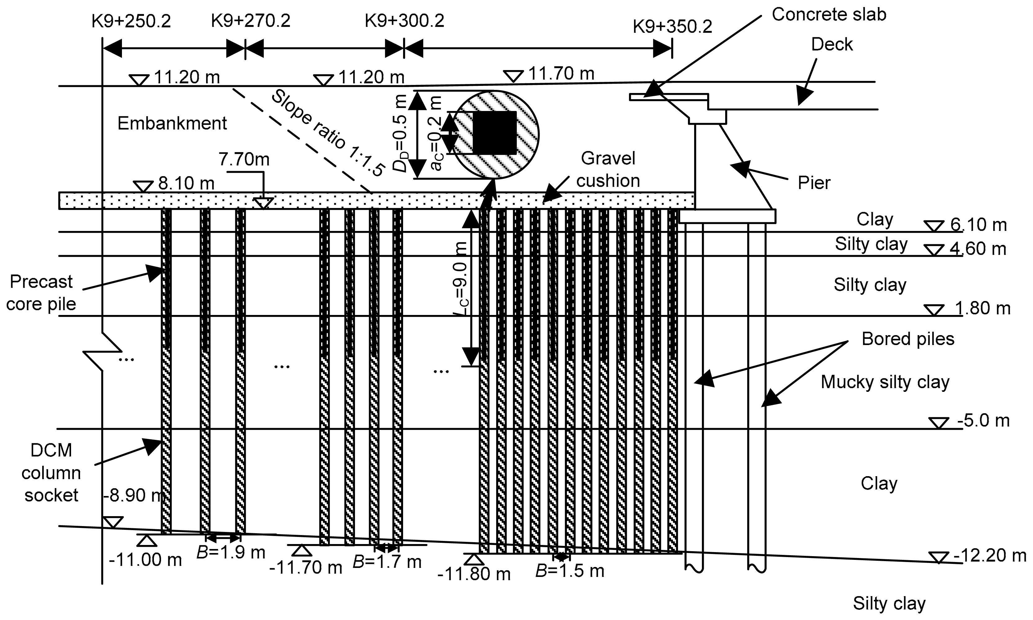
Three test sites denoted as Site A (K9+350.2–K9+300.2), Site B (K9+300.2–K9+270.2), and Site C (K9+270.2–K9+250.2) were reinforced by concrete-cored DCM piles at the southern approach of the Xiao Ying-Jiang River Bridge as shown in Fig. 2. Site D (K9+098–K9+118) was reinforced by DCM columns and was located close to the above three test sites. Pile parameters at the four test sites are shown in Table 1. B is the pile spacing, and aC is the side length of precast core pile.
Fig.2 Illustration of concrete-cored DCM pile
Table 1
Pile parameters of test sites
Test site
Soil improvement method
DCM column socket
Precast core pile
B (m)
LD (m)
DD (mm)
LC (m)
aC (mm)
A
Concrete-cored DCM pile
19.5
500
9
200
1.5
B
Concrete-cored DCM pile
19.4
500
9
200
1.7
C
Concrete-cored DCM pile+geotechnical grille
18.7
500
9
200
1.9
D
DCM column
19.1
500
1.5
The four test sites were used as farmland before the expressway construction. The ground elevation after leveling is 7.7 m above the mean sea level. The ground water level is about 1.3 m below the ground surface.
With the results of static cone penetration tests (CPTs) and laboratory tests on the undisturbed soil samples, the soil profile at the four test sites are similar and can be divided generally as follows: No. 1, clay, 0–1.6 m, gray yellow, with Fe-Mn nodules, with plastic; No. 2–1, silty clay, 1.6–3.1 m, gray, with plastic; No. 2–2, silty clay, 3.1–5.9 m, gray, doping orientation of Mica, with flow plastic; No. 2–3, mucky silty clay, 5.9–12.7 m, gray, doping humus and argillaceous nodules, with flow plastic; No. 2–4, clay, 12.7–19.9 m, gray, doping humus, with soft plastic; No. 3, silty clay, 19.9–23.6 m, gray, with plastic. The engineering properties of the soils with depth in the construction site are shown in Fig. 3. The engineering parameters of the soft clay at the test site are as follows: unit weight γ=17.9–19 kN/m3; water content w=28.7%–37.7%; void ratio e=0.84–1.09; elastic modulus Es=3.1–12.9 MPa; cohesion of consolidation undrained (CU) test ccu=10.2–21.3kPa; friction angle of CU test Φcu=14.5°–21°; the number of standard penetration tests (SPT) N=3–13; and specific penetration resistance of static cone penetration (CPT) ps=0.62–2.79 MPa.
Fig.3 Soil properties at four test sites
3. Field test program
3.1. Plate load tests
To obtain the ultimate bearing capacity of composite ground reinforced by concrete-cored DCM piles, plate load tests on single pile composite foundations were conducted on three concrete-cored DCM piles (the numbers of test piles at Site A are C-DCM1, C-DCM2, and C-DCM3) and three DCM columns (the numbers of test piles at Site D are DCM1, DCM2, and DCM3) at 28 d after pile installation.
3.2. Instrumentation for long-term observation
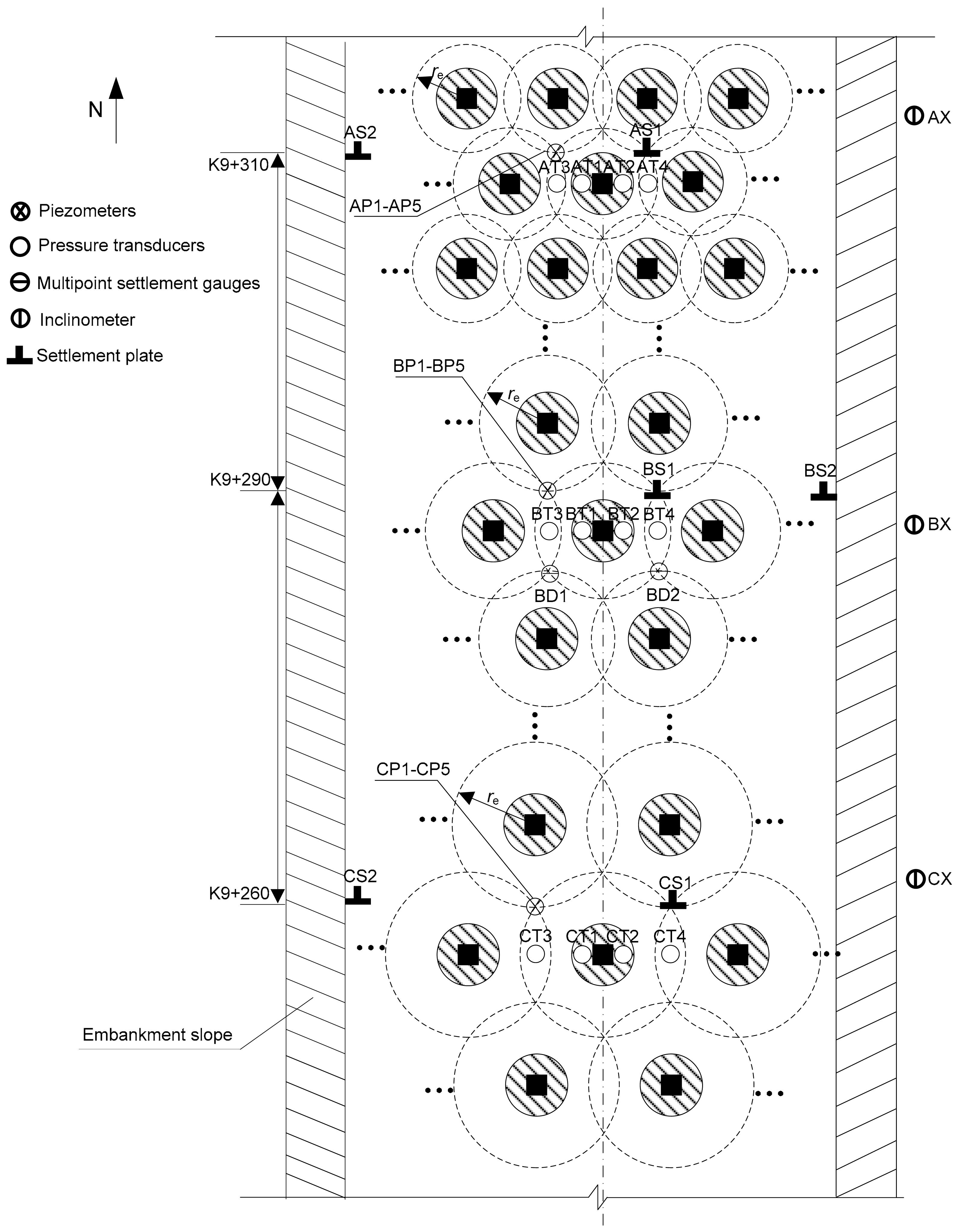
To estimate the effect of foundation reinforcement and obtain the engineering characteristics of a concrete-cored DCM pile composite under embankments, monitoring instruments including settlement plates, multipoint settlement gauges, inclinometers, piezometers, pressure transducers, and steel stress meters were installed at three test sites (Site A=K9+310, Site B=K9+290, Site C=K9+260) as shown in Fig. 4 and Fig. 5. Due to similar locations of instruments at the three test sites, except that there were no multipoint settlement gauges at Site A and Site C, details of Site B are described as follows as an example.
Fig.4 Planar graph of instruments locations
Fig.5 Sectional profile of instruments locations at Site B
Total settlements of composite foundations were measured by using settlement plates. The settlement plate with a square section 0.5 m×0.5 m in area was welded to a spiral steel tube which was jointed in length for easy observation during embankment filling. One settlement plate (BS1) was placed on the surface of the gravel cushion in the middle of three piles, at about 0.85 m east of the center line of the embankment. The other one (BS2) was placed under the east edge of the embankment slope top at the same elevation as BS1.
The settlement of the surrounding soil at different depths was recorded using multipoint settlement gauges. Two multipoint settlement gauges (BD1 and BD2) with a length of 20 m were installed symmetrically among three piles, at about 0.85 m east of the center line of the embankment.
The deep lateral movement of the composite foundations at the toe of the embankment was measured by an inclinometer. The inclinometer tube (BX) with a length of 20 m was installed at about 0.5 m east of the embankment toe. The lateral movement underground can be obtained at every 0.5 m in length.
Five piezometers at a depth of 3 m (BP1), 6 m (BP2), 9 m (BP3), 15 m (BP4), and 20 m (BP5) were used to measure the variation of pore pressure during embankment fill. Five piezometers were also installed in the middle of three piles, about 0.85 m west of the center line of the embankment.
Two pressure transducers (BT1 and BT2) were embedded on the top of the DCM column socket symmetrically at about 0.1 m from the center line of the embankment, and two (BT3 and BT4) were set on the surface of the surrounding soil.
Eighteen steel stress meters were welded onto the reinforcing steel of the precast core piles symmetrically at a depth of 0.2 m, 1.3 m, 1.9 m, 2.7 m, 3.5 m, 5.4 m, 6.3 m, 7.0 m, and 9.0 m, respectively.
Finally, to compare the foundation treatment effect and load transfer law of a foundation reinforced by a concrete-cored DCM pile and DCM column, monitoring instruments including settlement plates, inclinometers, piezometers and pressure transducers were also installed at Site D. The locations of instruments at Site D were similar to those at Sites A, B, and C.
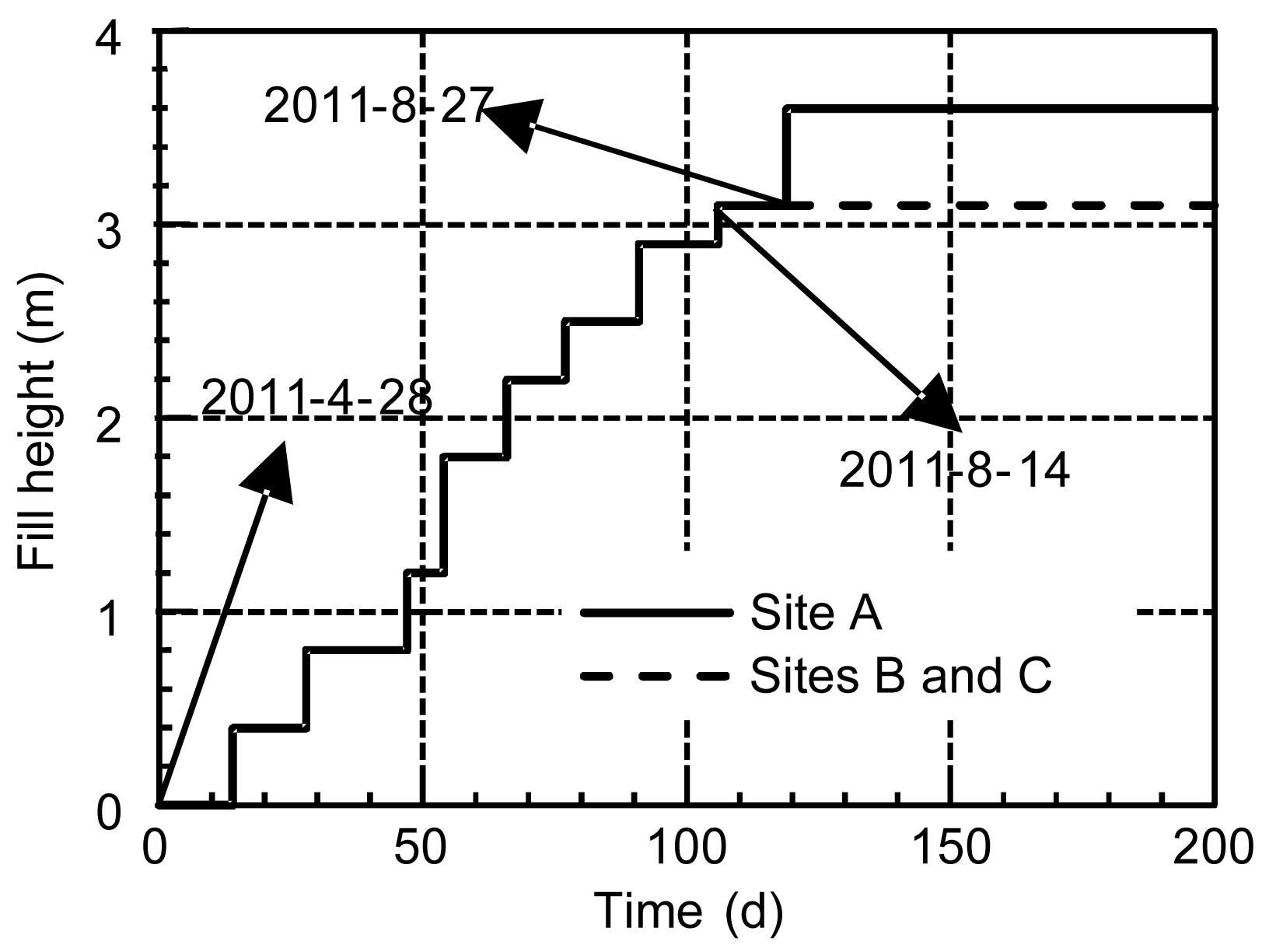
The embankment fill process of three of the test sites is shown in Fig. 6. Embankment fill at all four test sites began on Apr. 28, 2011, and finished on Aug. 27th, 2011 at Site A, Aug. 14, 2011 at Sites B and C, and Sept. 11, 2011 at Site D. The final embankment height was 3.6 m at Site A, and 3.1 m at Sites B, C, and D.
Fig.6 Fill height versus time
4. Test results
4.1. Ultimate bearing capacity
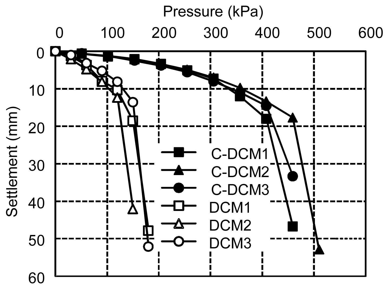
The pressure-settlement (P-S) curves of the composite foundations are shown in Fig. 7. As shown in the P-S curve, the settlement of the concrete-cored DCM pile composite foundation is less than that of the DCM column composite foundation under the same upper load.
Fig.7 P-S curves of PLT
With an increase in upper load, the difference in settlement between concrete-cored DCM piles and DCM column foundations is increasing. It can be seen that the settlement control effect of concrete-cored DCM piles is greater than that of DCM columns, especially under a large upper load. The failure of the composite ground is considered to have occurred when there is a reduction stage in P-S curves. The load at the reduction stage is defined as the ultimate bearing capacity of the composite ground. The average ultimate load of the concrete-cored DCM pile composite foundation (425 kPa) is about 3.3 times that of the DCM composite foundation (130 kPa). Although the limitation of the load plate area leads to a finite transferring depth of load in PLT, it is demonstrated that due to the insert of precast core piles with higher compression modulus and shear strength, the bearing capacity and settlement control effect of the concrete-cored DCM pile composite foundation is better than that of the DCM column composite foundation.
4.2. Load sharing ratio
The load sharing ratio of the composite foundation reinforced by concrete-cored DCM piles is defined as ,
,
,
,
where σC, σD, and σs are the vertical stresses on the top of precast core piles, DCM column sockets, and surrounding soil, respectively. nC, nD, and ns are the load sharing ratios of precast core piles, DCM column sockets, and surrounding soil, respectively. AC, AD, and As are the sectional areas of precast core piles, DCM column sockets, and surrounding soil, respectively.
As shown in Fig. 8, with the increase in fill height, the load sharing ratio of surrounding soil decreases, whereas the load sharing ratio of the precast core pile increases. That is to say, with an increase in upper load, more and more vertical load is amassed on the precast core piles. Although the sectional area of the precast core pile is smaller than that of the surrounding soil, the load sharing ratios on the precast core piles are 0.42, 0.30, and 0.38 respectively at Sites A, B, and C at the completion of embankment fill.
Fig.8 Load sharing ratio of concrete-cored DCM pile composite foundation in Site A (a), Site B (b), and Site C (c), and Site D
During the whole filling process, there is little variation in the load sharing ratio of the DCM column socket, which has a value of 0.2 (Figs. 8a–8c). This indicates the role that the DCM column socket plays in the transfer of shear stress from the precast core pile to the surrounding soil.
At Site A, the DCM column sockets and precast core piles bear about 70% of the upper load together, while at Site D, which has the same replacement ratio, the DCM column only bears about 42% of the upper load (Fig. 8d). Therefore, compared to the DCM column site, the concrete-cored DCM pile bears greater upper load, and there was less embankment loading acting on the surrounding soil.
The distribution of skin friction between surrounding soil and pile is an important parameter in design (Poorooshasb et al., 1996) and can be discussed from the test results of pile axial force. Fig. 9 shows the axial force of the precast core pile with depth in Site A, Site B, and Site C. It can be seen that the precast core pile stress initially increases and then decreases with depth. This indicates that under a flexible load, such as an embankment, soil settlement at the upper section of a composite foundation is greater than at a pile. Stress of the surrounding soil is transferred to the pile, then at the upper end of the pile negative friction occurs. After reaching a specific depth (approximately 0.3Lc in this study), the settlement of the pile body is greater than that of the surrounding soil, therefore the vertical stress of the pile body is transferred to the surrounding soil by means of skin friction. However, in PLT with a rigid load plate, vertical stress of a precast core pile decreases linearly with increasing depth (Dong et al., 2004). Note that the distribution law of skin friction of concrete-cored DCM piles under an embankment is different from that found in the PLT.
Fig.9 Axial force of precast core pile with depth in Site A (a), Site B (b), and Site C (c)
4.3. Excess pore pressure
Figs. 10a–10d show the variation in excess pore pressure with time at Sites A, B, C, and D. The weight per volume of the embankment is taken as 19 kN/m3, and the embankment load at Site A is approximately 68 kPa, while that of Sites B, C, and D is 59 kPa. It can be seen that at Sites A, B, and C, which were reinforced by concrete-cored DCM piles, the maximum excess pore pressure in the surrounding soil is 11 kPa, 12 kPa, and 15 kPa, respectively. This indicates that most of the embankment load is borne by the concrete-cored DCM piles, resulting in low excess pore pressure. The difference in the maximum excess pore pressure at Sites A, B, and C is caused by different replacement ratios. During the filling process, the Site A foundation has the maximum replacement ratio but the minimum excess pore pressure. Excess pore pressure in a foundation decreases with an increase in replacement ratio. This is consistent with the observation that a concrete-cored DCM pile bears more upper load than a DCM column (Fig. 8). Excess pore pressure is lower at Sites A, B, and C than at Site D.
Fig.10 Excess pore pressure versus time in Site A (a), Site B (b), Site C (c), and Site D (d)
4.4. Settlement
Total settlement occurring during the embankment filling process is shown in Fig. 11. With the greatest thickness of soft clay and fill height, greater settlement occurred at Site A than at Sites B and C. By combining the geotechnical grille, the settlement at Site C is the smallest at three concrete-cored DCM pile treatment sites. There is no steep reduction in settlement curves, which demonstrates that the stability of ground during the embankment filling process is expected.
Fig.11 Comparison of settlement between composite ground reinforced by concrete-cored DCM pile and DCM column
With the assumption that the rate of settlement decreases hyperbolically with time after time tA (tA is suggested to be half of the total fill time), the relationship between settlement and time can be given by (Yin et al., 2007) ,
where t is the fill time, St and S∞ are the settlements at time t and final settlement, respectively, and α is a parameter.
Combining the observed settlement data, the fitting curve between (t−tA)/St and (t−tA) is obtained. The gradient and intersection of the fitting curve are 1/S∞ and α/S∞, respectively. The average predicted final settlement (S∞) at Sites A, B, and C are 100.8 mm, 108.9 mm, and 67.2 mm, respectively, which are all smaller than that at Site D. Post-construction settlements (Sp) can be calculated as final settlements minus settlements measured before pavement construction (Sc). As shown in Table 2, the average post-construction settlement values of Sites A, B, C, and D are 13.7 mm, 25.3 mm, 10.1 mm, and 37.0 mm, respectively. The first three values are 37.0%, 68.3%, and 27.3% of the value for Site D. The above analysis results indicate that the use of concrete-cored DCM piles is a more practical method to reduce final and post-construction settlements of the expressway than with DCM columns.
Table 2
Settlements at test sites
Site
Sc (mm)
S∞ (mm)
(mm)
Sp (mm)
A
AS1
82.8
95.2
100.8
12.4
13.7
AS2
91.4
106.4
15.0
B
BS1
85.5
113.6
108.9
28.1
25.3
BS2
81.8
104.2
22.4
C
CS1
58.9
69.4
67.2
10.5
10.1
CS2
55.2
64.9
9.7
D
DS1
131.5
169.5
161.7
38.0
37.0
DS2
117.8
153.8
36.0
The settlement of surrounding soil with depth in the concrete-cored DCM pile zone in Site B is shown in Fig. 12. The total settlement of the foundation reinforced by concrete-cored DCM piles can be divided into three components: (1) the settlement (S1) of composite foundation within the length of the precast core pile (mm), (2) the settlement (S2) of composite foundation between the bottom of the precast core pile and DCM column socket (mm), and (3) the settlement (S3) of soft soil beneath the concrete-cored DCM piles (mm).
Fig.12 Soil settlements versus depth measured by BD1 (a) and BD2 (b)
At the end of embankment filling (Aug. 14, 2011, the average values of S1, S2, and S3 measured by BD1 and BD2 were 20.5 mm, 40.5 mm, and 5 mm, respectively. Sevnty-one days after the completion of embankment fill, the average values of S1, S2, and S3 were 25 mm, 50.5 mm, and 6.5 mm, respectively. S1, as a proportion of total settlement, is only 33.6% at the end of embankment fill and 30.4% 71 d after the completion of embankment fill. That is to say, with the insertion of precast core piles, S1 can be reduced because the modulus of the composite foundation within the length of the precast core pile increases greatly.
Vertical load exists at the bottom of the precast core pile (Fig. 10), and transfers from the bottom of the precast core pile downward. The vertical stress increases consequently in the composite foundation which goes downward from the bottom of the precast core pile. Furthermore, observations from settlement readings at various depths also indicate that a large compression occurs on the foundation at the bottom of the precast core pile. For example, S2 is 57.9% of total settlement on the 71st day after completion of filling. However, the large compression mentioned above is only in comparison with S1. In fact, because of the existence of the DCM column beneath the bottom of the precast core pile, the compression of the composite foundation is smaller than that of a natural foundation.
Settlement in the soft soil beneath the DCM column socket (S3) is only 11.7% of the total settlement, because the concrete-cored DCM pile limits the transfer depth of vertical stress effectively. Most of the settlement takes place within the length of the concrete-cored DCM pile, and there is less settlement occurring in the substratum.
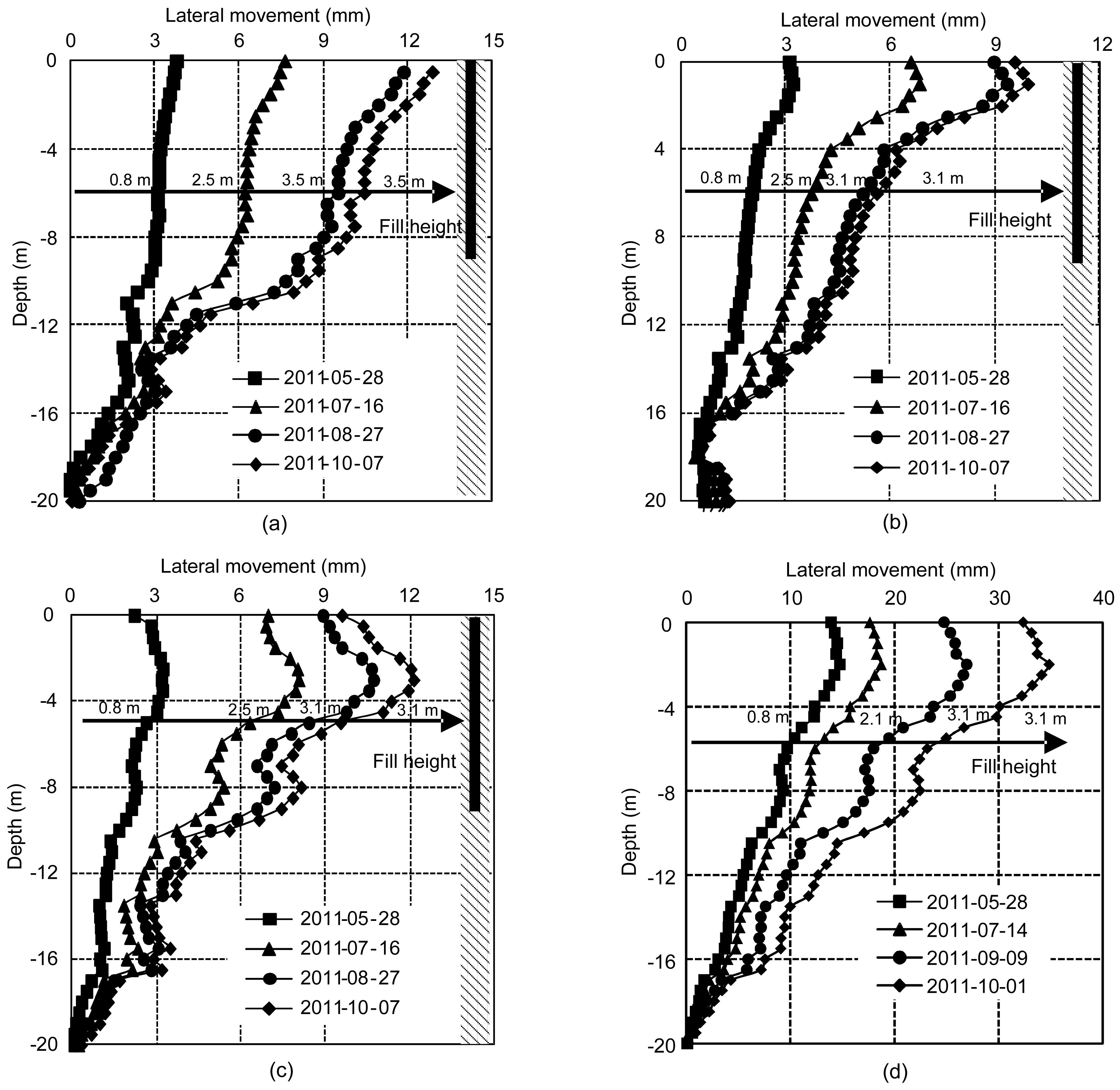
4.5. Lateral movement
Fig. 13 shows the soil lateral movement with depth below the toe of the embankment at Sites A, B, C, and D. It can be seen that although the embankment was filled to between 3.1 m and 3.6 m, the lateral movement caused by the fill in the concrete-cored DCM pile composite foundation was low. The largest lateral movement of the soft clay layer for Sites A (12.85 mm), B (9.95 mm), and C (12.1 mm) is much less than that for Site D (34.85 mm). The results are consistent with the PLT, load sharing ratio, excess pore pressure and settlement measurements, mainly because of the higher compression modulus and shear strength of precast core piles at Sites A, B, and C.
Fig.13 Lateral movement with depth in Site A (a), Site B (b), Site C (c), and Site D (d)
The ratio of the maximum lateral displacement measured at the embankment toe to the maximum total settlement at the embankment centerline is defined as the lateral displacement ratio, which is a good indicator of embankment stability (Indraratna et al., 1992; Chai et al., 2002). The smaller the lateral displacement ratio, the better the embankment stability. At completion of the embankment, the lateral displacement ratios for Sites A, B, C, and D are 0.12, 0.09, 0.17, and 0.23, respectively. The lower lateral displacement ratios for Sites A, B, and C indicate that concrete-cored DCM pile-supported ground enhances the embankment stability better than the conventional DCM column-supported ground.
5. Conclusions
In this study, several field testing programs were conducted to compare ground treatment effect and engineering characteristics of a composite foundation reinforced by a concrete-cored DCM pile and DCM columns. On the basis of field tests results, the following conclusions can be obtained:
Based on PLT for a single pile, the ultimate bearing capacity of the concrete-cored DCM piles is more than three times that of the DCM column composite foundation. It is shown that the concrete-cored DCM piles yield a stiffer foundation than the conventional DCM columns.
Compared to the DCM column site, the concrete-cored DCM piles bear more upper load, and there is less embankment loading acting on the surrounding soil. Consequently, the excess pore pressure in the concrete-cored DCM pile composite foundation is lower than that in a conventional DCM column composite foundation.
Under variable embankment loads, negative friction occurs at the upper section of the pile. The distribution law of skin friction of concrete-cored DCM piles under embankment loading is different from the result using PLT.
Post-construction settlement of the concrete-cored DCM pile composite foundation is 37.0% (Site A), 68.3% (Site B), and 27.3% (Site C) of the post-construction settlement of the conventional DCM composite foundation (Site D). Moreover, the lateral displacement ratio of the concrete-cored DCM pile composite foundation is 0.12 (Site A), 0.09 (Site B), and 0.17 (Site C), smaller than that of the conventional DCM composite foundation (Site D). This indicates that the concrete-cored DCM pile-supported embankment performed better because it induced less deformation in both vertical and lateral directions under embankment loading.
The field study indicates that concrete-cored DCM piles provide a viable and technologically sound solution for soft ground improvement under embankment loads when compared with conventional DCM columns.
[1] Arulrajah, A., Abdullah, A., Wo, B.M., 2009. Ground improvement techniques for railway embankments. Ground Improvement, 162(1):3-14.
[2] Borges, J.L., Domingues, T.S., Cardoso, A.S., 2009. Embankments on soft soil reinforced with stone columns: numerical analysis and proposal of a new design method. Geotechnical and Geological Engineering, 27:667-679.
[3] Chai, J.C., Miura, N., Shen, S.L., 2002. Performance of embankments with and without reinforcement on soft subsoil. Canadian Geotechnical Journal, 39(4):838-848.
[4] Chen, J.J., Zhang, L.Y., Zhang, J.F., 2012. Field tests, modification, and application of deepsoil mixing method in soft clay. Journal of Geotechnical and Geoenvironmental Engineering, 139(1):1-11.
[5] Dong, P., Qin, R., Chen, Z.Z., 2004. Bearing capacity and settlement of concrete-cored DCM pile in soft ground. Geotechnical and Geological Engineering, 22(1):105-119.
[6] Han, X.J., Xu, B.F., 2000. Study on the bearing capacity behavior of the excavated belled piles on the complicate old gully site. Chinese Journal of Geotechnical Engineering, (in Chinese),22(1):77-82.
[7] Indraratna, B., Balasubramaniam, A.S., Phamvan, P., 1992. Development of negative skin friction on driven piles in soft Bangkok clay. Canadian Geotechnical Journal, 29(3):393-404.
[8] Johnson, S.J., 1970. Precompression for improving foundation soils. Journal of Soil Mechanics and Foundation Engineering Division, 96(1):111-114.
[9] Lin, K.Q., Wong, I.H., 1999. Use of deep cement mixing to reduce settlements at bridge approaches. Journal of Geotechnical and Geoenvironmental Engineering, 125(4):309-320.
[10] Lorenzo, G.A., Berga, D.T., 2003. New consolidation equation for soil-cement pile improved ground. Canadian Geotechnical Journal, 40(2):265-275.
[11] Poorooshasb, H.B., Alamgi, M., Miurab, N., 1996. Negative skin friction on rigid and deformable piles. Computers and Geotechnics, 18(2):109-126.
[12] Six, V., Mroueh, M., Shahrour, I., 2012. Numerical analysis of elastoplastic behavior of stone column foundation. Geotechnical and Geological Engineering, 30(4):813-825.
[13] Suematsu, N., Isooda, T., Kanda, Y., 1984. Construction of highway on soft ground. Seminar on Soil Improvement and Construction Techniques in Soft Ground, Japanese Society of Soil Mechanics and Foundation Engineering,:144-157.
[14] Yin, Z.Z., 2007. Geotechnical Principle. (in Chinese), Hydraulic and Hydropower Press,Beijing :
[15] Zhou, J.J., Wang, K.H., Gong, X.N., 2013. Bearing capacity and load transfer mechanism of a static drill rooted nodular pile in soft soil areas. Journal of Zhejiang University-SCIENCE A (Applied Physics & Engineering), 14(10):705-719.
Open peer comments: Debate/Discuss/Question/Opinion


Open peer comments: Debate/Discuss/Question/Opinion
<1>