Affiliation(s):
1.
The State Key Lab of Fluid Power Transmission and Control, Zhejiang University, Hangzhou 310027, China; moreAffiliation(s): 1.
The State Key Lab of Fluid Power Transmission and Control, Zhejiang University, Hangzhou 310027, China; 2.
School of Information and Engineering, Zhejiang Radio & Television University, Hangzhou 310027, China; less
Yong Li, Jin Wang, Guo-dong Lu, Guo-jun Pan. A numerical study of the effects of roller paths on dimensional precision in die-less spinning of sheet metal[J]. Journal of Zhejiang University Science A, 2014, 15(6): 432-446.
@article{title="A numerical study of the effects of roller paths on dimensional precision in die-less spinning of sheet metal", author="Yong Li, Jin Wang, Guo-dong Lu, Guo-jun Pan", journal="Journal of Zhejiang University Science A", volume="15", number="6", pages="432-446", year="2014", publisher="Zhejiang University Press & Springer", doi="10.1631/jzus.A1300405" }
%0 Journal Article %T A numerical study of the effects of roller paths on dimensional precision in die-less spinning of sheet metal %A Yong Li %A Jin Wang %A Guo-dong Lu %A Guo-jun Pan %J Journal of Zhejiang University SCIENCE A %V 15 %N 6 %P 432-446 %@ 1673-565X %D 2014 %I Zhejiang University Press & Springer %DOI 10.1631/jzus.A1300405
TY - JOUR T1 - A numerical study of the effects of roller paths on dimensional precision in die-less spinning of sheet metal A1 - Yong Li A1 - Jin Wang A1 - Guo-dong Lu A1 - Guo-jun Pan J0 - Journal of Zhejiang University Science A VL - 15 IS - 6 SP - 432 EP - 446 %@ 1673-565X Y1 - 2014 PB - Zhejiang University Press & Springer ER - DOI - 10.1631/jzus.A1300405
Abstract: die-less spinning eliminates the dependence upon the mandrel of traditional spinning, but bringing about comparatively poor dimensional accuracy which needs to be improved. In this paper, roller paths in the first pass of die-less spinning, including concave, convex, linear and combined ones are parameterized according to the degree of bending and their effects on dimensional precision (thickness variation and shape deviation) have been studied by using experiments of finite element (FE) analysis. The effects of roller paths on thickness variation, shape deviation, tool forces, and stress and strain variations have been analyzed numerically. The results showed that for concave roller paths, the thickness variation is not very sensitive to the degree of bending, while a low degree of bending of the roller path can result in a low shape deviation. For convex roller paths, a low degree of bending leads to both low thickness reduction and low shape deviation. Further research shows that a combined roller path with convex-concave curve could contribute a low shape deviation, while an inverse combined roller path gives better thickness precision.
Darkslateblue:Affiliate; Royal Blue:Author; Turquoise:Article
Article Content
1. Introduction
Sheet metal spinning is a traditional forming process for axially symmetric metal components. Its properties, such as chipless manufacture, strain hardening, and smaller deformation force load as well as the incremental forming features, make it be an effective method for producing complex and thin-walled components (Wong et al., 2003). By using a mandrel in the forming process, accurate manufacturing can be achieved, but to do so also limits the application of traditional metal spinning because of the cost of the mandrel and the limitation to axially symmetric products. Thus, new spinning technologies have been proposed to eliminate these limitations. Die-less spinning is one of them, which tries to eliminate the dependence upon the mandrel of traditional spinning, but leads to comparatively poor dimensional accuracy that needs to be improved.
Traditional sheet metal spinning is mainly divided into two parts: conventional spinning and shear spinning, in which the metal plate is gradually formed onto the mandrel by a roller. Conventional spinning, as shown in Fig. 1a, is defined as the process with a constant thickness t0 but a changeable diameter D1. Shear spinning, as shown in Fig. 1b, is defined as a process with a constant diameter D0 but a changeable thickness t1 that can be determined by
,
where a is the inclination angle of the wall of the part, as shown in Fig. 1b.
Fig.1 Diagrams of conventional spinning (a), shear spinning (b), and die-less spinning (c) (Runge, 1994; Kawai et al., 2001; Music et al., 2010)
In contrast, die-less spinning, as shown in Fig. 1c, is a process in which the metal plate is formed by the roller freely rather than formed onto the mandrel. The function of the general mandrel is just to fix the rotating plate. It is similar to conventional spinning but eliminates the limitations of the mandrel, thereby considerably broadening the range of the application of the process.
Although the definitions of conventional and shear spinnings are different, Kang et al. (1999) indicated that the deformation modes of these two processes are similar, and thickness reduction happens in both conventional spinning and shear spinning, especially in the first pass of the process.
In research on shear spinning, many studies have concentrated on the prediction of wall thickness variations by using the sine law and investigation of the effects of process parameters, such as roller geometry, feed ratio, and rotation speed, on the roller forces and products quality through experimental trials and finite element (FE) methods (Chen et al., 2001; Zhang et al., 2012; Sekiguchi and Arai, 2012). Similar research has also been published on conventional spinning. Quigley and Monaghan (2000) investigated the forming characteristics of conventional spinning by comparing its results with those of shear spinning, and concluded that there is some degree of shear forming in the first roller path of conventional spinning but the strains are much less than those in shear spinning.
Both experimental and FE methods are widely used in research on forming technologies such as traditional spinning. Gao and Fang (2005) utilized an FE method to investigate the effects of friction on the final thickness distribution in order to get a uniform thickness in sheet metal after processing. Wang and Long (2011a) carried out an experiment with 5-passes conventional spinning to investigate the deformation properties of the process and showed the normal forces and stress patterns in a successful process. Essa and Hartley (2010) concentrated on the study of the effects of the main process parameters on the quality of conventional spinning products. The design of experiments (DOE), analysis of variance (ANOVA) and min-max optimization procedure were used in their studies, which showed that feed rate, relative clearance, and roller nose radius are the most important working parameters for the quality and precision of products. A similar method was proposed by Xie et al. (2007) for multi-response quality analysis in sheet metal forming. Some studies were also proposed (Wang et al., 2011) to get the information on the wrinkling appearance in the conventional spinning process.
The roller path which plays a crucial role in the quality of products in the conventional spinning has been studied by many researchers. Hayama et al. (1970) picked up four types of roller profiles, including linear and circular ones, and concluded that an involute curve is an excellent profile for improving the forming limits of materials in conventional spinning. Liu et al. (2002) investigated the first-pass of conventional spinning and got the same results as Hayama et al. (1970). They also concluded that the first-pass plays a decisive role in the wall thickness distribution in the final work piece. Wang and Long (2011b) carried out 3D FE analysis of the effects of roller paths (linear, concave, convex, and combined curve) on the variation of wall thickness, tool forces, and stresses in depth. They suggested that the dominant in-plane tensile radial strains may be the main reason for the wall thinning. However, the roller paths in previous studies are usually only defined qualitatively. In addition, most of them has just studied the different effects of the various roller path curves themselves, and been little concerned about the final products. This greatly limits the application of those research results.
The die-less spinning which was proposed by Kawai et al. (2007) is developed from the conventional spinning. Kawai et al. (2001) developed the process by research on the die-less spinning of truncated conical shells and hemispherical shells. They showed that the sine law is also realized in the die-less spinning of conical parts, but the hemispherical parts have little shear spinning properties. In addition, the dimensional accuracy of the products is always poorer than in those produced by the traditional spinning process. Liu et al. (2002) developed a 3D FE model to analysis the process of multi-pass die-less spinning process, and Matsubara (2001) applied it to the incremental forming of sheet metal and verified its effectiveness experimentally.
The die-less spinning process has a greater potential for application compared to conventional ones, especially for the flexible production of complex products. However, research is insufficient to allow it to be applied in industrial production at the moment. As in research on conventional spinning, roller paths are the dominant parameters, affecting the dimensional accuracy of products in die-less spinning. Although roller paths in conventional spinning have been studied by many researchers, the deformation mode of die-less spinning is different and the dimensional accuracy of the products in die-less spinning will be more sensitive to the parameters because of the loss of the mandrel and the increasing possibility of springback. In addition, the planning strategy for the roller paths in the multi-pass die-less spinning of complex products is also unknown and little research has been undertaken in this area.
In this study, we investigated the effects of the parameterized roller paths on the dimensional accuracy of the first pass of die-less spinning by using FE analysis with commercial LS-DYNA software. Different roller paths were parameterized by bending degrees as in the ratio of chord height to length (RHL) of the curves, including linear, concave, convex, and combined paths that are the basic roller path curves for complex products. The effects of different RHL paths on tool forces, wall thickness variations and shape deviations of the products were studied and the stress and strain variations in die-less spinning were analyzed numerically. Then the properties of both the concave and convex roller paths were established, providing a foundation for multi-pass planning and dimensional accuracy improvement in die-less spinning in later studies.
2. Methodology
2.1. Setting of basic parameters
The first pass of die-less spinning with different types of roller paths was analyzed in this study. Fig. 2 is a schematic diagram of spinning experiments similar to the model studied by Wang and Long (2011). Except that the dimension of the blank was slightly different with a diameter of 240 mm and thickness of 1 mm. The data from Wang and Long (2011) was used to verify the FE simulation results of this work in Section 3. A feed rate of 800 mm/min and a spinning die speed of 400 r/min were used in the study.
Fig.2 Schematic diagram of the spinning experiment (unit: mm)
2.2. Roller paths parameterization and shape deviation definition
The roller paths defined in the previous studies were almost always qualitative and specific to the individual research which means the results have little use in revealing universal effects between the roller paths and the product qualities. In this study, the roller paths including concave, linear, convex, and combined curves are all defined as three times Bezier curves, which make the definition and planning of the roller path much easier by taking the advantage of properties of convenient curve definition, shape change, and curve montage. In addition, all the Bezier curves used in the study have been parameterized by the RHL to get generalized effects of the roller paths on the dimensional precision of die-less spinning products.
The definition of the three time Bezier curve is: ,
where u∈[0,1] and V(i) are control points.
The bending degree, RHL of the Bezier curves (Fig. 3a) is defined by ,
where P1, P2, P3, and P4 are the four control points of the Bezier curve and are distributed uniformly. P1P4 is the chord length of the curve, and M1M2 is the average chord height of the curve. (±) indicates that RHL is positive for a convex curve and negative for a concave curve.
Fig.3 Schematic diagram of roller paths and shape deviation definition (a) RHL definition; (b) Linear, concave, and convex paths; (c) Combined paths; (d) Shape deviation definition
All irregular and complex sheet products in the spinning process can be summarized as concave, convex or combined products. The multi-roller paths designed for die-less spinning should have the same property as the particular product, which means concave roller paths cannot be used in die-less spinning for the production of convex products. This paper focuses on the first-pass of die-less spinning and studies the relationship between the dimensional precision and RHL of the curves in different conditions with concave, convex, and combined roller paths, in order to provide a foundation for later roller path compensation and multi-pass designing of the relevant products.
Seven representative roller paths parameterized by Bezier curve have been selected in this study. As shown in Fig. 3b, they are a linear roller path (with an inclination angle of β) and three convex and three concave roller paths in a Bezier equation with different RHL. In addition, two combined roller paths including a com1 (concave+convex) curve and a com2 (convex+concave) curve have also been used in a further investigation as shown in Fig. 3c. The RHL of each roller path is shown in Table 1.
Table 1
Roller paths and the corresponding RHL (β=30°, λ=tan5°/3)
Roller path
RHL
Concave
C-cav3
−2λ
C-cav2
−1.5λ
C-cav1
−λ
Line
0
Convex
C-vex1
λ
C-vex2
1.5λ
C-vex3
2λ
Combined
Com1
−λ to +λ
Com2
+λ to −λ
In die-less spinning, the particular mandrel is replaced by a general one, so springback effects will be much more severe than in traditional metal spinning, leading to significantly dimensional variation in the products. The dimensional precision in this study therefore includes both thickness and shape variation. Thickness variation is defined as the thickness of the cross section of a product, while shape variation is defined as the deviation between the roller paths and the actual generatrix of the parts after the process (Fig. 3d), which could also be used as a reference for improving shape accuracy in future studies and applications.
2.3. Finite element analysis
2.3.1. Finite element method
The die-less spinning process is a nonlinearity problem which includes large deformation, dynamic changes, and complex contact conditions. At the same time, because of the comparatively large elastic deformation in die-less spinning, the springback phenomenon is more significant, and much affects the shape dimension of the product. Thus, we applied explicit and implicit finite element method (FEM) to simulate each of them in order to get more confident results.
1. Explicit FEM simulation
The explicit FEM provided by commercial FE software LS-DYNA was chosen to analyze the forming process, as it is more robust and efficient for complicated problems, such as dynamic events, nonlinear behaviors, and complex contact problems. Cauchy’s equation of motion is the basis of the dynamic-explicit finite element formulation, which can be written in an FE form as ,
where M is the nodal mass matrix, F is the vector of the internally included element force, P is the vector of the externally applied force and is the vector of nodal acceleration.
The acceleration is solved by the explicit time integration procedure, using the central difference rule. Then, the change of velocity is calculated by ,
where tn is the calculation time in step of n.
The displacement at the end of the increment is determined by integration of the velocity and the displacement at the beginning of the increment: .
Using this type of method, the die-less spinning forming process can be simulated effectively with the aid of LS-DYAN commercial software.
2. Implicit FEM simulation
The implicit FEM is ideal for the simulation of static problems. In die-less spinning, after the process of forming, the blank will have a comparatively large springback because the blank is not held by the mandrel. The springback process is a quasi-static problem and has no complex contact situations. So we import the explicit FEM results of the process into the standard module of the LS-DYNA software to analyze the springback phenomenon of the blank.
2.3.2. Finite element modeling and parameters setting
The roller and mandrel in die-less spinning are modeled as 3D discrete rigid bodies and the holder which presses the blank on the mandrel is replaced by restraints on the nodes in the central parts of the blank, leaving only rotational freedom in the axial axes, so as to improve the computational efficiency. The metal blank is the only deformable component and is meshed by a 3D T-shell element (Fig. 4), which is similar with the research of (Wang and Long, 2011b). There are 4320 elements and 9000 nodes on the blank in the FE model.
Fig.4 Finite element simulation model of die-less spinning (a) Beginning stage; (b) Processing stage
The elastic properties of the metal blank are calculated by Young’s modulus as 198.2 GPa, the Poisson’s ratio as 0.3, and the mass density is 7861 kg/m3. The true stress-strain curve of the metal blank is shown in Fig. 5. Temperature and rate effects are neglected in this study. Coulomb friction is set up with a friction coefficient of 0.2 between the blank and the mandrel and 0.02 between the blank and the roller. To speed up the FE solution, the mass scaling method with a scaling factor of 15 was used in all models. Fig. 4 shows the two stages of die-less spinning process for different manufacturing times.
Fig.5 True stress-strain curve of mild steel
In addition, to obtain the dimensional precision of the blank after the process, the springback effects have also been simulated by transferring the explicit analysis results to the implicit analysis with the standard module of ANSYS/LS-DYNA. Fig. 6 shows the effects of springback on residual stress variations and the shape variation of the final product. The amount of residual stresses decreases significantly and also distributes evenly according to Figs. 6a and 6b. The shape variation also has an obvious deviation after springback according to Fig. 6c, which will be considered and analyzed in Section 4.
Fig.6 Illustration of springback condition of the final product von Mises stress variations before springback (a) and after springback (b); (c) Deviations of the product shape after springback
3. Results
3.1. Verification of the simulation
FE analysis models have been verified by studying the energy histories of die-less spinning processes (LSTC, 2008; Li et al., 2013). To ensure that mass scaling does not significantly affect the simulation results, the kinetic energy of the blank should not be greater than 10% of the internal energy during the process. At the same time, the ratio of the hourglass energy to the internal energy should also be less than 5% to avoid the hourglass problem, which results in a shear locking phenomenon in the reduced integration linear elements and affects simulation accuracy. As shown in Fig. 7, the ratio of the kinematic energy to internal energy is extremely high at the beginning of the process because the rotational acceleration of the blank plays a crucial role at that time. The ratio decreases significantly after a processing time of 0.5 s, from the beginning of the deformation of the blank. Thereafter, the ratio remains constantly and is much smaller than 10%. At the same time, the ratio of the hourglass energy to the internal energy is below 5% throughout the process. Therefore, the problems caused by mass scaling and hour glassing are well controlled in the model.
Fig.7 Evaluation of energy ratio in finite element model of linear roller path
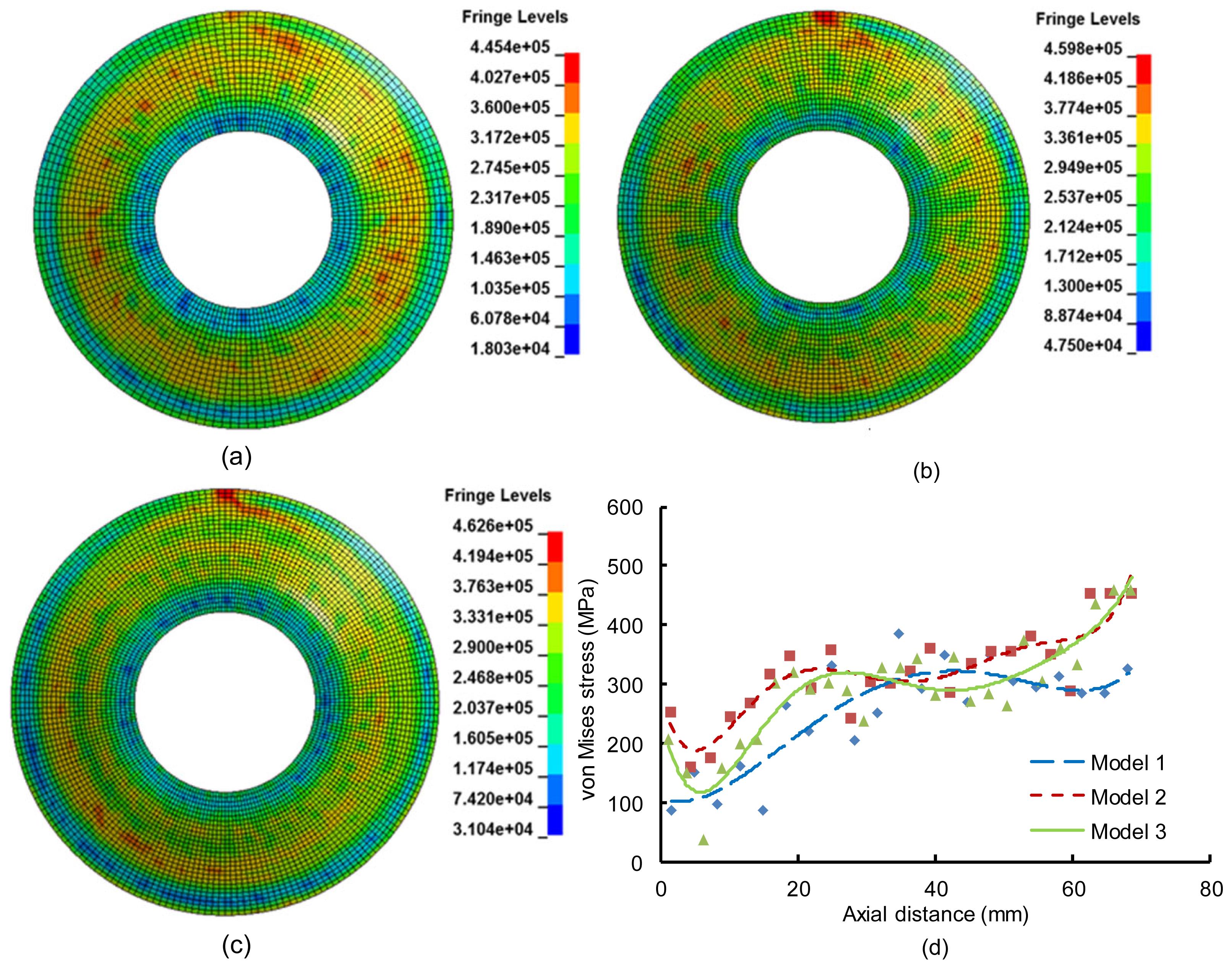
A grid independence study has also been carried out on the model with a linear roller path. Three models with different grid densities of the blank have been proposed and the distribution of the stresses has been analyzed as shown in Figs. 8a–8c. There is a 3.71% error in the largest stress between models 1 and 3, while the same error between models 2 and 3 is 0.61%. The comparison of the variation of von Mises stresses along roller traces of the blank is also shown in Fig. 8d. A good agreement between model 2 and model 3 has been observed and the average difference of stresses is 5.8%, while the difference between model 1 and model 3 is as high as 18.7%. Therefore, by analyzing the distribution and variation of the von Mises stresses among the three models, it is believed that grid independency can be achieved when using the grid density of FE model 2. Therefore, the grid density of that model has been used in the simulation of this study.
Fig.8 Variations of von Mises stress in finite element model of linear roller path (a) Model 1 (3150 elements); (b) Model 2 (4320 elements); (c) Model 3 (5400 elements); (d) Stress distribution along the roller trace of the blank
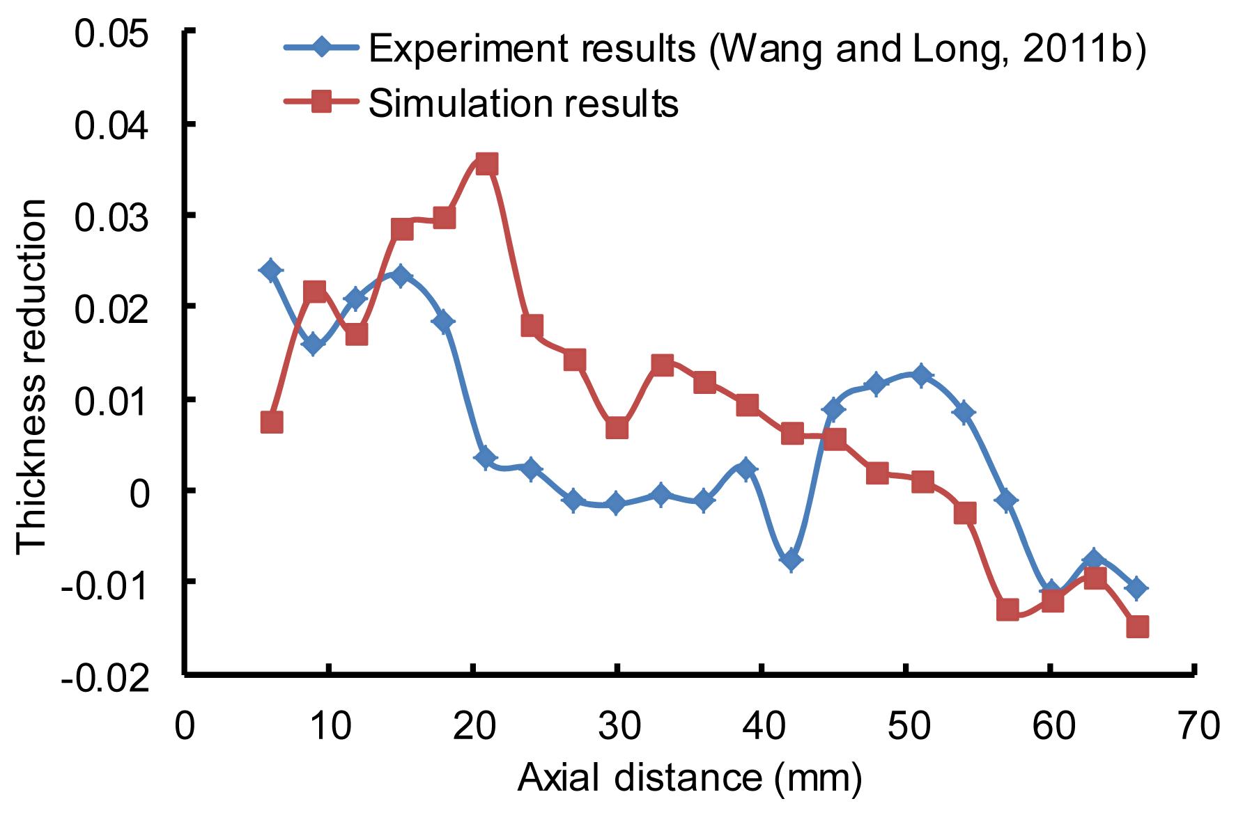
The simulation models have also been verified by comparing the results with experimental data. The simulation model in this study is similar to the work of (Wang and Long, 2011b) and the results of the thickness variation of the blank with the same linear roller path have been picked up. As shown in Fig. 9, the thickness reduction results in this study have been compared with the experimental results from (Wang and Long, 2011b). The results show a good agreement with each other and have a maximum error of 3.2%, which is reasonable. The errors may result from the differences in the thickness of the blank in the two models and the equivalent conditions used in the FE simulation, such as the constant friction coefficient and the using of a general mandrel in die-less spinning.
Fig.9 Comparison of the thickness variation of products in the linear roller path
3.2. Tool forces
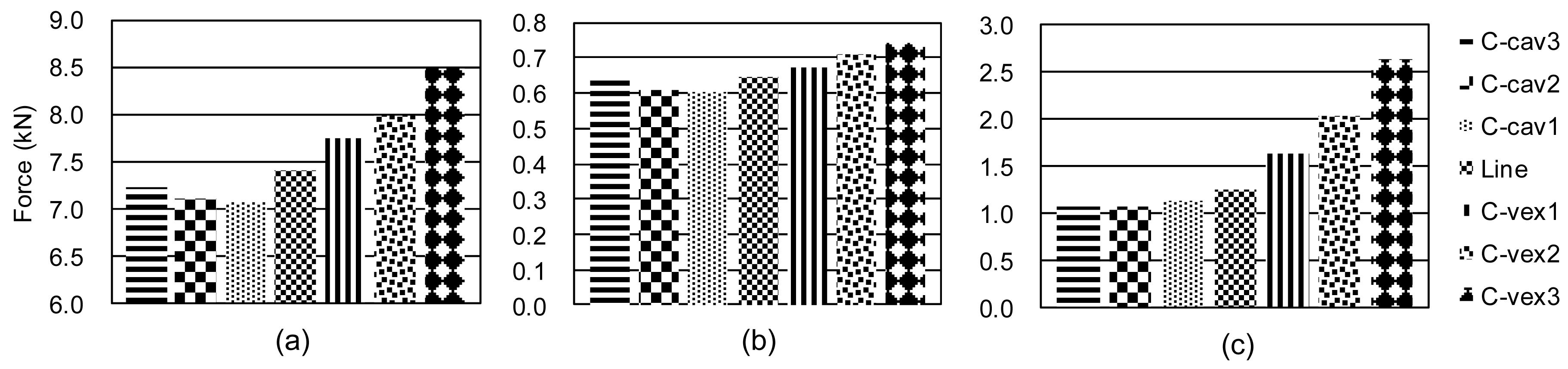
In this study, the axial force is defined in line with the axial of the mandrel and the radial force is defined along the radius of the mandrel. As shown in Fig. 10, the maximum axial forces are the highest among the three force components for all the roller paths, while the maximum tangential forces are the lowest ones, which is in agreement with the previous studies on conventional spinning (Matsubara, 2001; Essa and Hartley, 2010; Wang and Long, 2011a). The amount of the three maximum force components with concave roller paths changes only slightly when the RHL of the roller paths ranges from −2λ to −λ. However, for the convex roller paths, the maximum forces become significantly larger with the increase of the RHL.
Fig.10 Comparison of maximum tool forces with different roller paths (a) Axial force; (b) Tangential force; (c) Radial force
Table 2 shows the ratios of the maximum force components with the seven roller paths. It can be observed that the ratios of the maximum axial forces to the tangential forces generally remain around 11.5:1, while the ratios of the maximum radial forces to the tangential forces are changeable and the ratios become larger with the increase of the RHL of the roller paths, specifically 1.67:1 for the lowest RHL of −2λ with the concave roller path C-cav3 and 3.55:1 for the highest RHL of 2λ with the convex roller path C-vex3. The results are different from those of (Wang and Long, 2011b). That may be because of the different definitions of roller paths applied, but the tendency of the ratios among the three force components is similar.
Table 2
Ratios of maximum force components with different roller paths
Roller path
Ratio of maximum forces, Fa:Fr:Ft
C-cav3
11.2:1.67:1
C-cav2
11.7:1.78:1
C-cav1
11.8:1.88:1
Linear
11.5:1.93:1
C-vex1
11.5:2.43:1
C-vex2
11.3:2.87:1
C-vex3
11.4:3.55:1
Fa: axial force; Fr: radial force; Ft: tangential force
3.3. Dimensional precision–thickness and shape variation results
Because of the lack of a mandrel in the die-less spinning process, the formed products will be more sensitive to dimensional precision in both thickness and shape. In this study, both aspects of the dimensional precision in die-less spinning were studied. We investigated the average dimensional data from the two orthogonal cross sections of the blank, trace 1 and trace 2 (Fig. 11).
1. Thickness variation results
The thickness variations along the blank of the seven models are shown in Fig. 12a. For all the roller paths, the greatest thickness reduction varies with different roller paths and increases with the increase of RHL of the roller path. At the same time, the point of the highest thickness reduction appears in the middle part of the blank with concave roller paths (C-cav1, C-cav2, C-cav3), while the location of the same point moves towards the edge of the blank when the roller paths become convex ones (C-vex1, C-vex2, C-vex3), as shown in the region A in Fig. 12a. That means the thinning phenomenon appears mainly in the middle part of the blank when the roller path is concave curves, and, on the contrary, with convex roller paths, the thinning phenomenon appears mainly in the back part of the blank.
The average thickness of the seven roller paths is shown in Fig. 12b. In general, the average thicknesses become smaller with the increase of RHL of the roller paths. The rate of decrease of the average thickness is more significant with the convex roller paths than that with the concave and linear ones. This means that thickness is more sensitive to the RHL of the roller path for convex paths.
2. Shape variation results
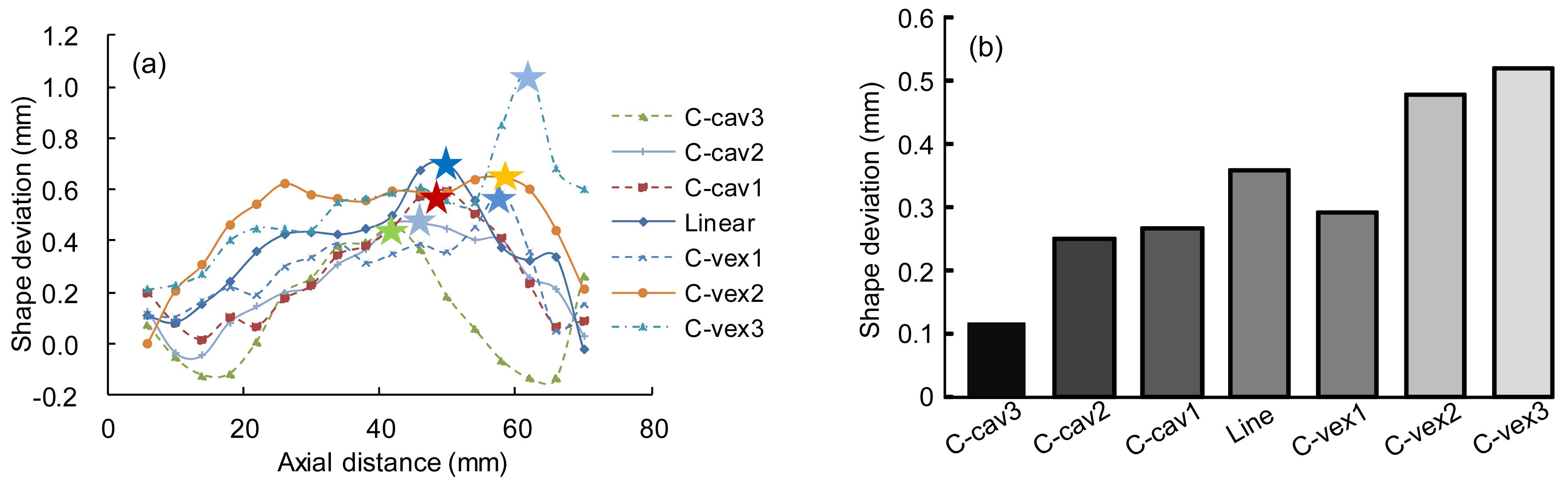
Fig. 13a illustrates the shape deviations along the blank with the seven roller paths of die-less spinning. For concave roller paths, the points of the highest shape deviation are located in the middle part of the blank. For convex roller paths, the points are located in the back part of the blank. In general, the points of the highest shape deviation move backwards gradually from the middle to the edge of the blank with the increase in RHL of the roller paths, which has the same trends as the greatest thickness reduction points. As illustrated in Fig. 13b, for the concave roller paths, the average shape deviation of the blank tends to be larger with the increase of RHL of the roller paths, although they are all smaller than that with the linear roller path. At the same time, the average shape deviations of the blank become larger with the increase of RHL for the convex roller paths. In addition, the shape precision seems to be worse than that with concave roller paths at a similar bending level.
Fig.11 Two orthogonal cross sections on the blank for dimensional precision data collection (a) Two traces on the blank; (b) Cross section of the traces
Fig.12 Thickness variation with different roller paths (a) Thickness variations along the blank; (b) Average thickness in each roller path
Fig.13 Shape variation with different roller paths (a) Shape deviation along the blank; (b) Average shape deviation in each roller path
It can be concluded that for concave roller paths, the thickness variation is not very sensitive to RHL of the path curve, but a low RHL of the roller path curve may result in low shape deviation. For convex roller paths, a low RHL of the roller path curve leads to both low thickness reduction and low shape deviation.
4. Discussion
4.1. Strain variations in the trials for dimensional precision conditions
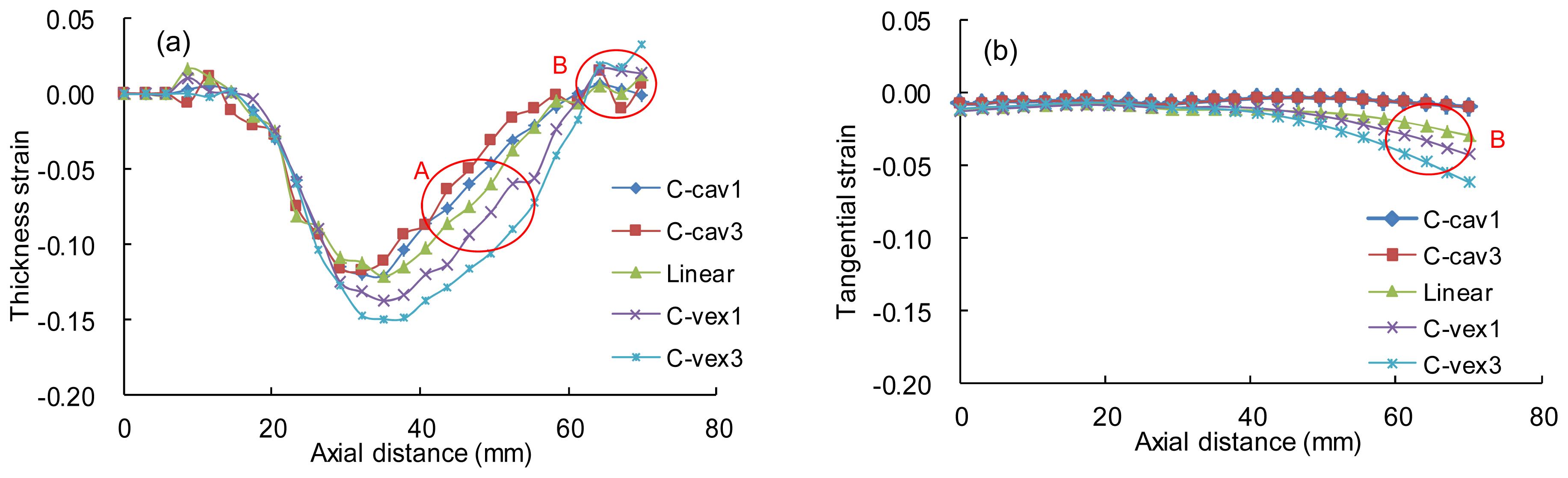
The variations of the thickness and tangential strain in different roller paths are shown in Fig. 14 for the analysis of dimensional precision conditions in Section 3.3. We chose five of them to analyze the results. As illustrated in Fig. 14a, the thickness strain variations have a similar changing trend as the thickness variation shown in Fig. 12a. The highest thickness strain becomes larger with the increase of RHL of the roller paths and increased thinning phenomena appear in the end parts of the blank with convex roller paths, as shown in area A in Fig. 14a. Fig. 14b shows that the blank is subjected to compressive tangential strains, which can lead to its thickening, especially at the end part of the blank in region B. The end part of the blank is also subjected to tensile thickness strains at the same region of B, resulting in a slightly thickened effect at the edge of the products.
Fig.14 Strain variations along the blank (a) Thickness strain; (b) Tangential strain
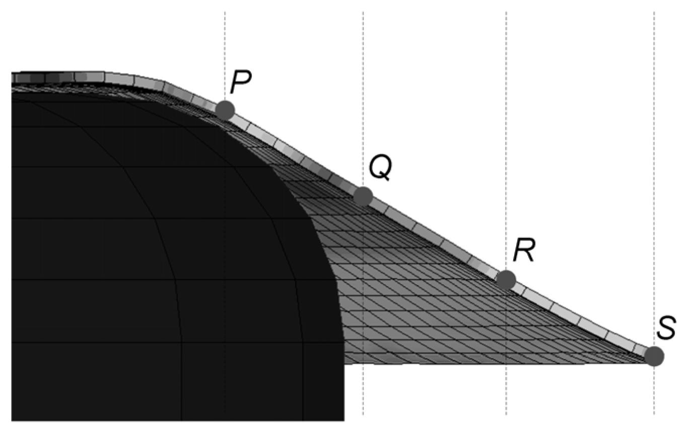
To further investigate dimensional variations and changing conditions during the die-less spinning process, a set of elements along the roller trace of the blank has been selected, as shown in Fig. 15. Element P is the first element freely deformed with no contact with the mandrel and element S is the last element at the end of the blank, elements Q and R are the trisection points on the blank between elements P and S.
Fig.15 Devised regions and selected elements along the blank
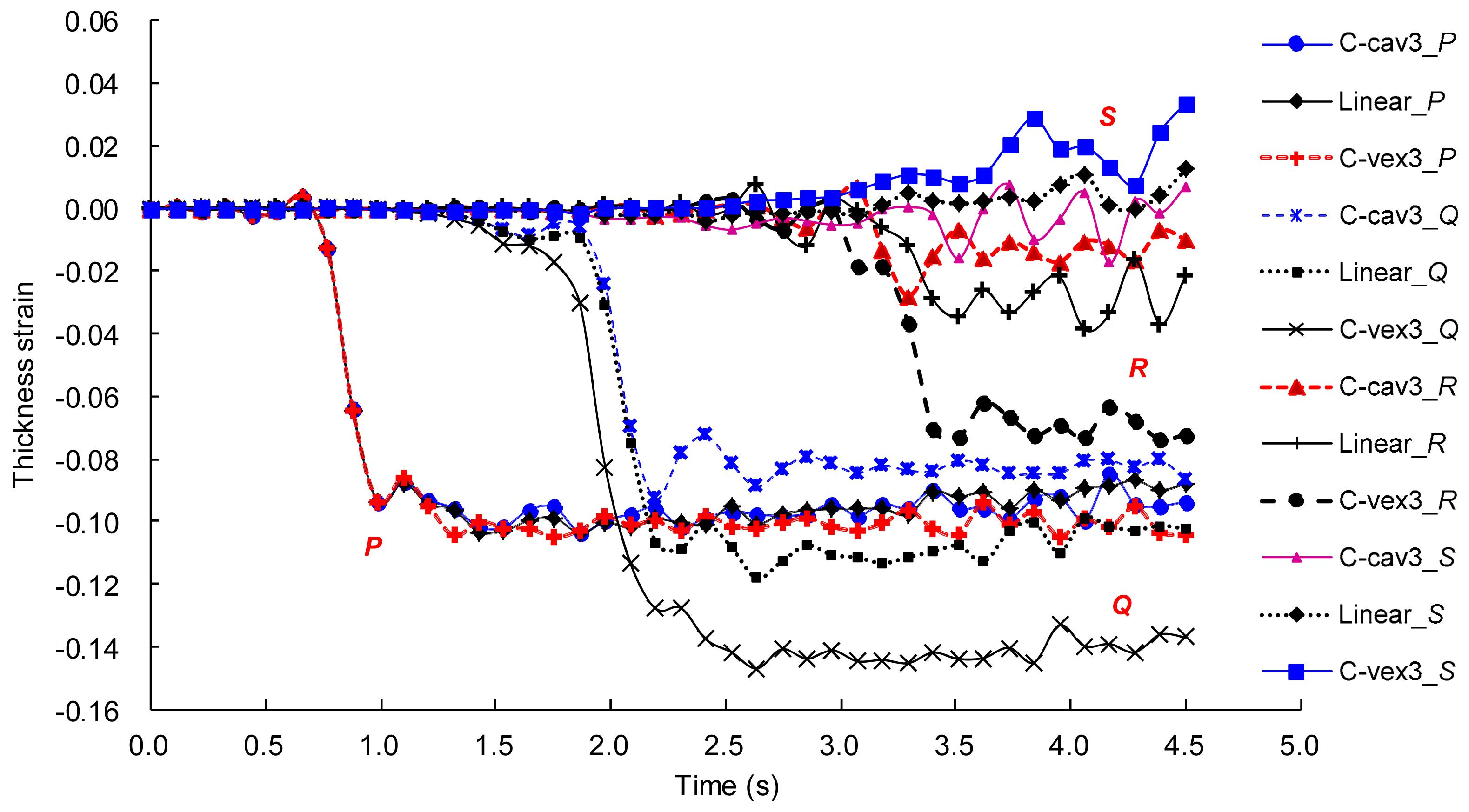
Fig. 16 shows the thickness strain variations of the selected elements above during the die-less spinning process. The representative concave, linear, and convex roller paths are studied. The variations of the thickness strains in the same element with different roller paths have similar changing conditions and especially in element P, even have similar values. The variations of element P remain almost the same in all the roller paths and the highest thinning point of the blank locates near this element with concave roller paths. The thickness strains in elements Q and R have the same increasing trend when the RHL of the roller paths becomes larger. The highest thinning point of the blank moves from element P to elements Q and R and the value becomes larger at the same time, which explains the thickness variations shown in Fig. 12a well. At the same time, in element S, there is a significant tensile thickness strain in the roller path of convex 3, which leads to a thickening phenomenon in the end part of the blank.
Fig.16 Comparison of thickness strain variation of the selected elements during the die-less spinning process
4.2. Stress variations of the trials for dimensional precision conditions
Fig. 17 shows the radial stress variations along the roller trace on the top and bottom surface of the blank after die-less spinning. Because the stress data are all from the discrete elements of the blank, we use a six-time polynomial to obtain the variation trend of the stress for analysis. The blanks with concave roller paths are subjected to lower stress values than those with linear and convex roller paths. As shown in Fig. 17, the top surface of a blank with concave roller paths is subjected to slight tensile radial stress in region A and slight compressive radial stress in region B, while the bottom surface of the blank is subjected to the opposite radial stress conditions. Two conversely directed radial bending effects in the back part of the blank are illustrated. At the same time, the radial stresses in the blanks with linear and convex roller paths are higher than those with concave ones and the back part of the blanks is subjected to a more apparent radial bending effect as shown in region C. The differences of the bending effects in the blank between the concave roller paths and convex ones are supposed to be one of the reasons for the different shape deviation conditions shown in Fig. 13a.
Fig.17 Radial stress variations after die-less spinning (a) Top surface of the blank; (b) Bottom surface
In addition, the highest radial stress point on a blank with concave roller paths is located in the middle part of the blank in region A, while the same points with linear and convex roller paths are located in the end part of the blank in region C, which is thought to be one of the reasons for the phenomenon of the highest shape deviation and thinning points moving gradually from the middle to the end of the blank with the increase of RHL of the roller paths, as shown in Figs. 12a and 13a.
Fig. 18 illustrates the axial stress variations of the blank with a representative five roller paths. In general, the axial stress is higher and the highest point of the axial stress curve moves backwards with the increase of the RHL of the roller paths.
Fig.18 Axial stress variations after die-less spinning (a) Top surface of the blank; (b) Bottom surface
For concave roller paths, the axial stresses along the blank seem to have a condition of vibration with a low average stress, which may result in a low shape deviation of the products as shown in Fig. 13a. For convex roller paths, the axial stress tends to be regular and comparatively large, in addition, it also becomes higher with the increase of RHL. That may explain the large average shape deviation condition of the blank with convex roller paths in Fig. 13b.
Elements Q and R in Fig. 15 have been chosen to investigate stress variations during the die-less spinning process. Axial stress variations of the selected elements Q and R during the die-less spinning process are shown in Fig. 19. Though the roller paths are various, the roller and the designated element of the blank will contact at the same time. So there is a similar axial stress variation before the contact happens. The value of the stress varies after contact. In general, with a higher RHL of the roller path, there is a larger axial stress in the blank. At the same time, the largest axial stress appears later with the increase of RHL, which results in a longer deformation time on the blank. That is in accord with the severe deformation (in both thickness and shape deformation) moving conditions shown in Figs. 12 and 13.
Fig.19 Radial stress variations of the selected element Q (a) and element R (b) during the process
4.3. Confirmation of the results and further investigation with combined roller paths
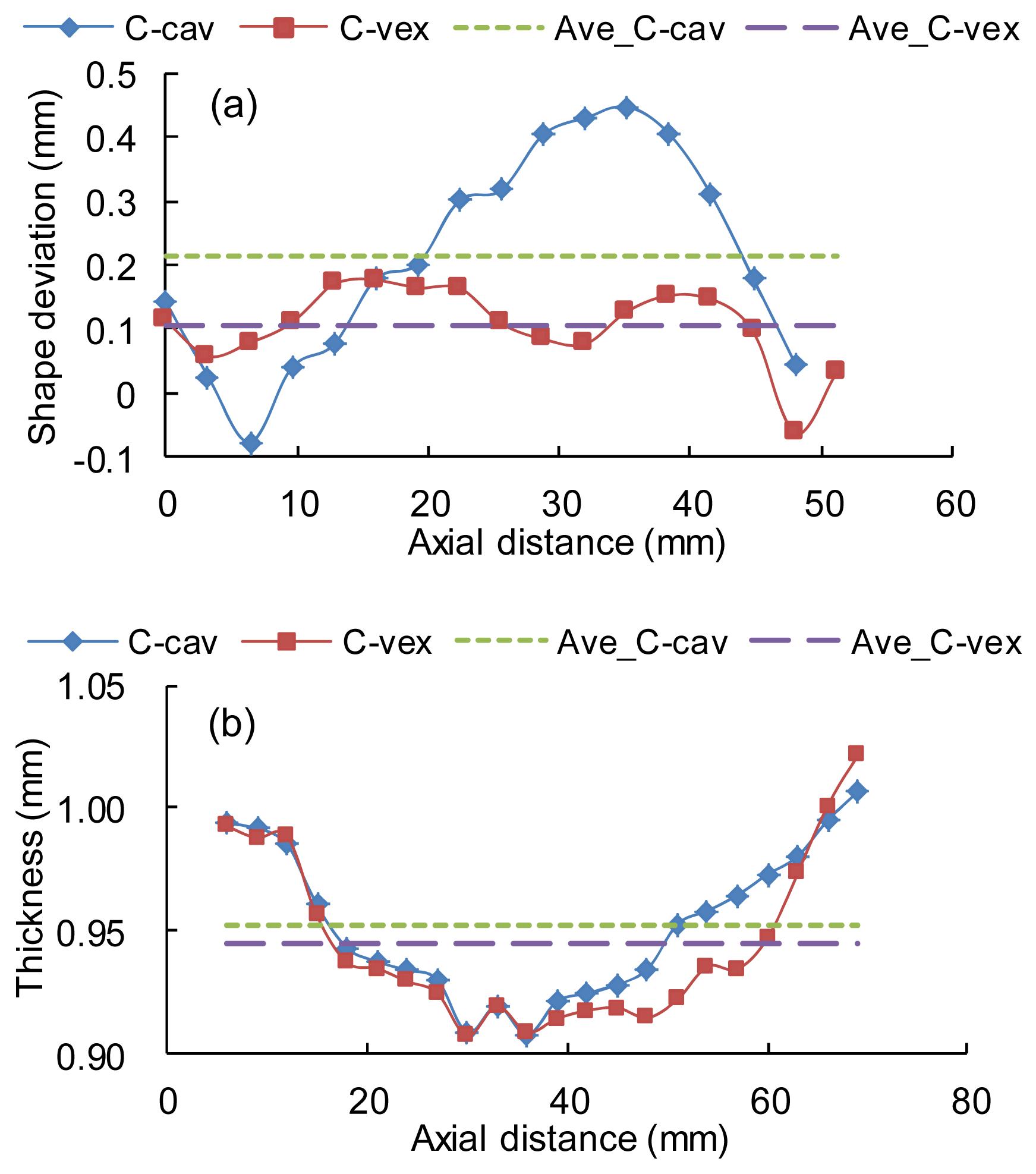
We added two models with concave and convex roller paths respectively to confirm the results mentioned above. A concave roller path with −0.5λ and a convex roller path with 0.5λ were chosen. The dimension precision results of the two models are shown in Fig. 20. The changing trend of the thickness variations and shape deviations are similar to the results shown in Figs. 12 and 13. For the concave path, the average thickness is 0.952 mm, which is nearly the same as the results of other concave roller paths, and the average shape deviation is larger than that for any other concave roller path above. For the convex path, the thickness and shape deviation condition are all better than the results for the other convex roller paths above. That is in good agreement with the results shown in Section 3.3 and could be an effective confirmation of them.
Fig.20 Comparison of dimensional variation with confirmation roller paths (a) Shape deviation and average deviation along the blank; (b) Thickness variation and average thickness along the blank
The concave, linear, and convex roller paths have been studied above and the results show that they have their own characteristics in the dimensional precision of the products in die-less spinning. The combined roller paths as shown in Fig. 3d have been investigated in this section. Fig. 21 shows the comparison of the dimensional precision of the products with roller paths of com1 and com2. As illustrated in Fig. 21, the standard deviation of the shape deviation variations of the products are 24.4% and 11.3% for com1 and com2 and the standard deviations of the thickness variations are 2.78% and 3.88%, respectively. The results show that the roller path of com2 contributes better shape precision, while the com1 has a better thickness variation but a worse shape precision. It is supposed that there is a slight contradiction between high thickness precision and high shape precision and the ideal state is to achieve a balanced condition between them.
Fig.21 Comparison of dimensional precision with further roller paths Shape deviation (a) and thickness variation (b) along the blank
5. Conclusions
Based on the FE analysis of the die-less spinning process in this study, the effects of quantitative roller paths (RHL of convex, linear, concave, and combined ones) on both the thickness variation and the shape deviation of the product have been studied. The following conclusions can be drawn regarding the process mentioned in Section 2, as shown in Table 3:
In general, in the first pass of a die-less spinning process, the forces are slightly affected by the RHL of the curves when the roller paths are concave ones. For convex roller paths, there is a significant increase of the forces when the RHL of the curves becomes higher.
For concave roller paths, the greatest thinning and shape deviation area is located mainly in the middle of the blank, and a low RHL could result in little shape deviation, while for the convex roller paths, the same areas are located mainly in the back part of the area and a low RHL leads to both low thickness reduction and low shape deviation.
The location of the highest compressive thickness strain which leads to a severe thinning phenomenon moves backwards from the middle part of the blank to the end part with the increase of the RHL of the roller paths. Meanwhile, the compressive tangential strain becomes significant at the end part of the blank, which helps to keep the edge of the products from thinning.
Two conversely directed radial bending effects in the back part of the blank have been observed in die-less spinning with concave roller paths, while a higher bending radial stress effect is shown with convex and linear roller paths, and this is proposed as the reason for different shape deviation results. At the same time, the axial stress becomes larger and the highest axial stress points move backwards with the increase of RHL, and have the same trend with the changing conditions of thickness.
The combined convex-concave roller path contributes better shape precision, while the inverse one (concave-convex) has a better thickness variation and a worse shape precision. That indicates that the ideal state is to achieve a balanced condition for both of them.
The results indicate the relationship between the parameterized roller paths and the dimensional precision in the first pass of die-less spinning. The effectiveness of the FE models has been shown, and that can be a foundation for further research on roller path compensation strategies and multi-pass planning methods in the die-less spinning of complex products.
Table 3
Influence of the bending degree (RHL) of roller paths on the forces and dimensional precision
[1] Chen, M.D., Hsu, R.Q., Fuh, K.H., 2001. Forecast of shear spinning force and surface roughness of spun cones by employing regression analysis. International Journal of Machine Tools & Manufacture, 41(12):1721-1734.
[2] Essa, K., Hartley, P., 2010. Optimization of conventional spinning process parameters by means of numerical simulation and statistical analysis. Proceedings of the Institution of Mechanical Engineers, Part B: Journal of Engineering Manufacture, 224(11):1691-1705.
[3] Gao, C.Y., Fang, Y.T., 2005. Investigation on the factors influencing the thickness distribution of superplastic-formed components. Journal of Zhejiang Universit-SCIENCE A, 6(7):711-715.
[4] Hayama, M., Kudo, H., Shinodura, T., 1970. Study of the pass schedule in conventional simple spinnning. Bulletin of JSME, 13(65):1358-1365.
[5] Kang, D.C., Gao, X.C., Meng, X.F., 1999. Study on the deformation mode of conventional spinning of plates. Journal of Materials Processing Technology, 91(1-3):226-230.
[6] Kawai, K., Yang, L.N., Kudo, H., 2001. A flexible shear spinning of truncated conical shells with a general-purpose mandrel. Journal of Materials Processing Technology, 113(1-3):28-33.
[7] Kawai, K., Yang, L.N., Kudo, H., 2007. A flexible shear spinning of axi-symmetrical shells with a general-purpose mandrel. Journal of Materials Processing Technology, 192-193:13-17.
[8] Li, Y., Wang, J., Lu, G.D., 2013. Three-dimensional finite element analysis of effects of roller intervals on tool forces and wall thickness in stagger spinning of thin-walled tube. Proceedings of the Institution of Mechanical Engineers, Part C: Journal of Mechanical Engineering Science, 227(7):1429-1440.
[9] Liu, J.H., Yang, H., Li, Y.Q., 2002. A study of the stress and strain distribution of first-pass conventional spinning under different roller-traces. Journal of Materials Processing Technology, 129(1-3):326-329.
[10] LSTC, 2008. LS-DYNA Keyword Users Manual. Version 971. Livermore Software Technology Corporation,Livermore, USA :
[11] Matsubara, S., 2001. A computer numerically controlled dieless incremental forming of a sheet metal. Proceedings of the Institution of Mechanical Engineers, Part B: Journal of Engineering Manufacture, 215(7):959-966.
[12] Music, O., Allwood, J.M., Kawai, K., 2010. A review of the mechanics of metal spinning. Journal of Materials Processing Technology, 210(1):3-23.
[13] Quigley, E., Monaghan, J., 2000. Metal forming: an analysis of spinning processes. Journal of Materials Processing Technology, 103(1):114-119.
[14] Runge, M., 1994. Spinning and Flow Forming (translated by Pollitt, D.H.). Leifeld GmbH,Ahlen, Germany :
[15] Sekiguchi, A., Arai, H., 2012. Control of wall thickness distribution by oblique shear spinning methods. Journal of Materials Processing Technology, 212(4):786-793.
[16] Wang, L., Long, H., 2011. Investigation of material deformation in multi-pass conventional metal spinning. Materials & Design, 32(5):2891-2899.
[17] Wang, L., Long, H., 2011. A study of effects of roller path profiles on tool forces and part wall thickness variation in conventional metal spinning. Journal of Materials Processing Technology, 211(12):2140-2151.
[18] Wang, L., Long, H., Ashley, D., 2011. Effects of the roller feed ratio on wrinkling failure in conventional spinning of a cylindrical cup. Proceedings of the Institution of Mechanical Engineers, Part B: Journal of Engineering Manufacture, 225(11):1991-2006.
[19] Wong, C.C., Dean, T.A., Lin, J., 2003. A review of spinning, shear forming and flow forming processes. International Journal of Machine Tools and Manufacture, 43(14):1419-1435.
[20] Xie, Y., Yu, H., Chen, J., 2007. Application of grey relational analysis in sheet metal forming for multi-response quality characteristics. Journal of Zhejiang University-SCIENCE A, 8(5):805-811.
[21] Zhang, J., Zhan, M., Yang, H., 2012. 3D-FE modeling for power spinning of large ellipsoidal heads with variable thicknesses. Computational Materials Science, 53(1):303-313.
Open peer comments: Debate/Discuss/Question/Opinion


Open peer comments: Debate/Discuss/Question/Opinion
<1>